3D Node by Two Projections |
  
|
The command can be called in one of the following ways:
Icon |
Ribbon |
|
Support Geometry > 3D Node > 3D Node by 2 Projections |
Keyboard |
Textual Menu |
<3KNJ> |
- |
Automenu of the |
|
<J> |
By Two Projections |
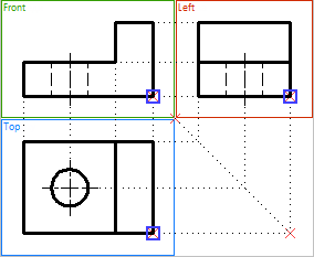
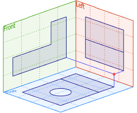
This method involves creating a 3D node based on its 2D projections – 2D nodes that lie on workplanes (surfaces).


There are two ways for creating a 3D node:
•Based on a single projection;
•Based on two projections.
After activating this method, the fields for setting source objects appear in the parameters window.
The current absolute coordinates of the 3D node being created (in the global coordinate system) are displayed on the Coordinates tab of the parameters window.-
3D Node by One Projection
To create a 3D node, you must specify a 2D node on the work plane (surface) or in the Model Elements window. The selected 2D node is displayed in the First Element field on the By Two Projections tab of the Parameters window. The Clear ![]() button enables you to cancel a node selection and to select another node.
button enables you to cancel a node selection and to select another node.
By default, the system attempts to automatically determine the work plane (surface) that the selected 2D node belongs to. The found workplane (surface) is displayed in the Worksurface field in the parameters window. You can cancel the workplane selection and re-select it using the Clear ![]() button.
button.

3D Node by Two Projections
To create a 3D node, select the 2D node of the first projection, then set the Second Projection flag and select the 2D node of the second projection. The specified 2D nodes are displayed in the corresponding fields of the parameters window. You can cancel the selection of the nodes and re-select them using the Clear ![]() button.
button.
Similar to the previous version of creating a 3D node (based on a single projection), the system tries to automatically determine the working planes (surfaces) that belong to the selected 2D nodes. The found planes (surfaces) are displayed in the corresponding fields of the parameters window. You can cancel the selection of the workplanes and re-select it using the Clear ![]() button.
button.

In this case, creating a 3D node may cause erroneous situations. The 3D node is created at the intersection of the perpendiculars to the workplanes that pass through the selected 2D nodes. If the perpendiculars do not intersect, the message "Projections do not form a 3D point" appears in the diagnostic window.