Sketch > Chamfer and Fillet |
  
|
Unlike the ribbon, chamfer and fillet options are grouped into a drop-down list in the automenu of the Sketch command. The presence of the drop-down list is indicated by the black triangle near an icon of an option displayed, when the list is folded. In order to unfold the list, either click ![]() a triangle
a triangle ![]() in the ribbon, or click and hold
in the ribbon, or click and hold ![]() on an icon of an option displayed, when the list is folded. This icon corresponds to an option used last in the current CAD session. When the Sketch command is launched, any option can be called via keyboard without unfolding the list.
on an icon of an option displayed, when the list is folded. This icon corresponds to an option used last in the current CAD session. When the Sketch command is launched, any option can be called via keyboard without unfolding the list.

When constructing chamfers and fillets, the existing graphic lines are modified, and new ones are formed. Select two lines and specify the chamfer or fillet parameters to create chamfers and fillets. In this case, the chamfer can be constructed only for straight intersecting lines. The rounding can be constructed for any lines.
Fillet
Icon |
Ribbon |
|---|---|
|
Draw > Sketch > Fillet Workplane > Sketch > Fillet |
Keyboard |
Textual Menu |
<SK>> |
|
Automenu of the |
|
<Shift>+<B> |
Fillet |
You can round any corner: straight, obtuse, sharp.

Also, using the Fillet command, you can create tangent arcs of a given radius between sketch lines that do not intersect, including parallel lines. The command supports following methods of fillet construction:
•Fillet of user-defined radius
•Fillet of the only possible radius
•Fillet of automatically adjusted radius
The command also provides the option of trimming initial lines.
The Fixed Radius checkbox is enabled by default in the command's parameters window.

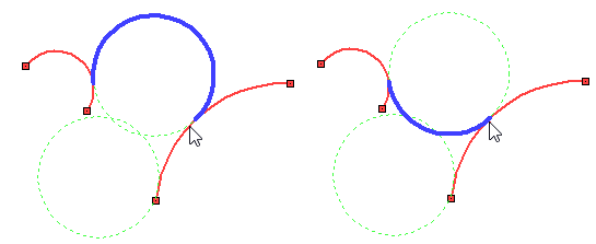
In such case, first you should type the desired value into the Radius input box. Next, select a first line by moving the cursor over it and pressing ![]() or <Enter>, then move the cursor over a second line. All variants of tangential circles of the specified radius, that can be constructed between the selected lines, will be automatically detected by the system and indicated in thin dashed lines. The initial lines are highlighted in red. A fillet may be constructed along any of these circles, with two possible trajectories of the fillet along each of the circles (by one and by other side of the tangency points). However, the system filters the possible trajectories, rejecting some of the variants as unacceptable (for example, if usage of a trajectory leads to constructing a loop). A circle with both possible trajectories available gets highlighted in green. A circle with only a single possible trajectory available gets highlighted in grey, if the current configuration of the fillet doesn't passes along it, or in blue otherwise. The preview of the current configuration of the fillet is displayed as a thick blue line. The first proposed configuration depends on the position of the cursor when selecting a line. In order to change the trajectory of the fillet along the current circle, press <R>.
or <Enter>, then move the cursor over a second line. All variants of tangential circles of the specified radius, that can be constructed between the selected lines, will be automatically detected by the system and indicated in thin dashed lines. The initial lines are highlighted in red. A fillet may be constructed along any of these circles, with two possible trajectories of the fillet along each of the circles (by one and by other side of the tangency points). However, the system filters the possible trajectories, rejecting some of the variants as unacceptable (for example, if usage of a trajectory leads to constructing a loop). A circle with both possible trajectories available gets highlighted in green. A circle with only a single possible trajectory available gets highlighted in grey, if the current configuration of the fillet doesn't passes along it, or in blue otherwise. The preview of the current configuration of the fillet is displayed as a thick blue line. The first proposed configuration depends on the position of the cursor when selecting a line. In order to change the trajectory of the fillet along the current circle, press <R>.

In order to switch to another circle, press <Z>.

Configurations of the fillet preview may also change automatically, when moving the cursor: the system selects the configuration nearest to the current position of the cursor.
Set the desired configuration of the fillet and press ![]() or <Enter> for constructing it.
or <Enter> for constructing it.
Fillet of the only possible radius
If the Fixed Radius checkbox is enabled, but there are no possible tangent circles of the inputted radius for the specified lines, then the preview of the fillet will not appear, upon moving the cursor over the second line. If you then try to finish the fillet creation by pressing ![]() or <Enter>, the result will depend on whether the specified lines are parallel to each other. If they're non-parallel, the command will output a message: "Cannot round with this radius" and the lines selection will be cleared. If they're parallel, then the system will ignore the specified Radius value, regardless of the status of the Fixed Radius checkbox, and the preview of the fillet will appear using the only possible radius value (half the distance between the specified lines). This value will be indicated in the Radius box of the parameters window, and the box will be non-editable. The preview will follow the cursor along the lines, so you have to specify its position by moving the cursor. If you want to switch the direction of the fillet arc, press <Z>. The direction may also change automatically, when moving the cursor. Set the desired configuration of the fillet and press
or <Enter>, the result will depend on whether the specified lines are parallel to each other. If they're non-parallel, the command will output a message: "Cannot round with this radius" and the lines selection will be cleared. If they're parallel, then the system will ignore the specified Radius value, regardless of the status of the Fixed Radius checkbox, and the preview of the fillet will appear using the only possible radius value (half the distance between the specified lines). This value will be indicated in the Radius box of the parameters window, and the box will be non-editable. The preview will follow the cursor along the lines, so you have to specify its position by moving the cursor. If you want to switch the direction of the fillet arc, press <Z>. The direction may also change automatically, when moving the cursor. Set the desired configuration of the fillet and press ![]() or <Enter> for constructing it.
or <Enter> for constructing it.

Fillet of automatically adjusted radius
If the Fixed Radius checkbox is disabled, then you should select two lines one by one by moving the cursor over them and pressing ![]() or <Enter>. Upon selecting the second line, the dynamically changing preview of the fillet will start following the cursor. The system automatically adjust the radius of the tangent circle, so that the fillet arc would pass through the position of the cursor. Two tangent circles of different radii may be possible for the same position of the cursor. In order to switch the circle, press <Z>.
or <Enter>. Upon selecting the second line, the dynamically changing preview of the fillet will start following the cursor. The system automatically adjust the radius of the tangent circle, so that the fillet arc would pass through the position of the cursor. Two tangent circles of different radii may be possible for the same position of the cursor. In order to switch the circle, press <Z>.

In order to switch the trajectory of the fillet arc along the current circle, press <R>.

The Radius box of the parameters window indicates the automatically adjusted value. The box stays editable, so you can type in a desired value at any moment. Upon manual input of a radius value, the command switched to the Fixed radius mode.
Set the desired configuration of the fillet and press ![]() or <Enter> for constructing it.
or <Enter> for constructing it.
The Trim Initial Lines checkbox is enabled by default in the command's parameters window.

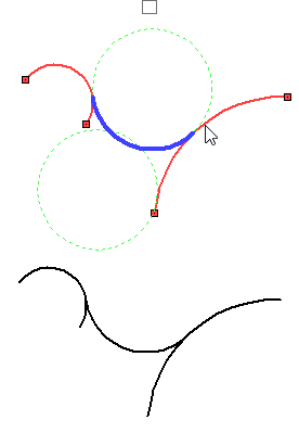
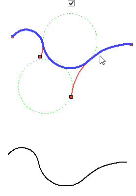
In such case, the initial lines will be trimmed at tangency points upon constructing a fillet. If the checkbox is disabled, the lines will remain unchanged. This option also affects the display of the fillet preview: when trimming is disabled, the thick blue line of the preview includes only the resulting arc; otherwise the preview also includes the sections of the initial lines to be kept upon trimming.


After constructing the fillet, the resulting line will be an arc. You can change the rounding radius only with the parameters available for the arc.
Icon |
Ribbon |
|---|---|
|
Draw > Sketch > Chamfer Workplane > Sketch > Chamfer |
Keyboard |
Textual Menu |
<SK>> |
|
Automenu of the |
|
<Ctrl>+<B> |
Chamfer |
A chamfer can be constructed between straight line segments that intersect at any angle.

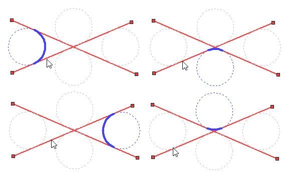
When the intersection of the segments is not at the point of their beginning or end, there are four options for constructing a chamfer. To select the necessary variant of chamfer construction, you have to select segments in the place where it is planned to create a chamfer. Lines beyond the chamfer can be trimmed or not trimmed, which is controlled by the Trim Initial Lines checkbox in the parameters window (by default, trimming of protruding lines is active).

If the lines do not intersect or the size of the chamfer is too large for the selected segments, then the chamfer cannot be built and a warning will be displayed.
After the chamfer is created, the resulting line will become a simple line segment. When editing a chamfer line, only line segment parameters will be available.
Three options for defining geometry are available in the chamfering command:
![]() Symmetrical chamfer
Symmetrical chamfer
![]() Chamfer by offset
Chamfer by offset
![]() Chamfer by angle and offset
Chamfer by angle and offset
To select the necessary type of chamfer in the parameters window, click on one of the three icons. The default is symmetrical chamfer. The selected type of chamfer changes the geometric parameters that must be specified for its construction.