Contour of Sweep |
  
|
Any object with wire or surface body geometry can be used as the original contour. A multi-contour 3D profile can be used as well. Sweeping a contour means placing its multiple instances along the selected path. A contour instance will be referred to as an intermediate section. To define an intermediate section, the system calculates orientation of the coordinate system of that intermediate section. The original coordinate system is calculated as the reference for the original contour orientation. A contour instance creation is done by transforming the original contour to the calculated coordinate system of a given intermediate section.
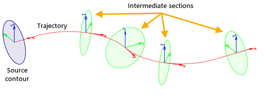
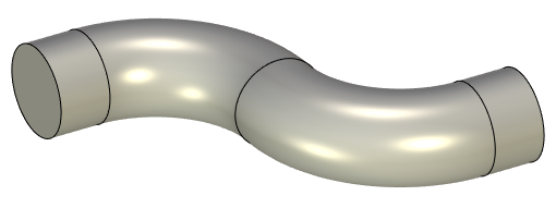
The original coordinate system is calculated at the start of the path. Two of its axes are set perpendicular to the path, and one is tangent to the path at the start point. The original contour position is fixed with respect to the original coordinate system. The contour sweeping is done by placing the original coordinate system together with the contour in other points of the path, in which the coordinate systems are defined for the intermediate sections.
Contour selection
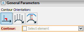
The first option that turns on automatically is the contour selection.
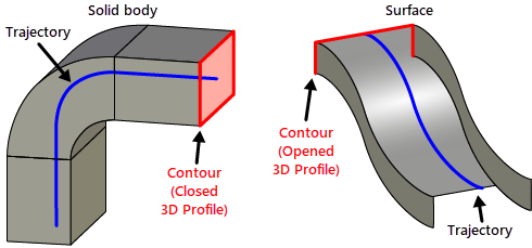
The option contains a set of selector filters helping selection of the desired objects. There is a pull-down list behind the icon that appears after prolonged pressing ![]() . A contour can be defined by any object with sheet or wire geometry, such as a 3D profile, 3D path, edge, face, surface, etc.
. A contour can be defined by any object with sheet or wire geometry, such as a 3D profile, 3D path, edge, face, surface, etc.
Control over contour orientation
Different geometry can be created, depending on the position of the intermediate sections with respect to the path. One of the three types of the contour orientation can be specified when creating the operation:
|
Perpendicular to the trajectory |
|
Parallel to the original profile |
|
By guides |
We recommend defining the contour orientation first, since that will determine the set of options offered by the system in the following steps.
Option selection is done in the parameters window of the operation, in the provided combo box with a pull-down list. The pull-down list contains all three possible ways of orienting the contour – Profile is perpendicular to path, Profile is parallel to source profile, By guides. The first and, apparently, the most often used setting is the system default. Therefore, if the contour is to be oriented perpendicular to the path, the contour orientation option selection can be skipped.
When using non-planar trajectory, condition of perpendicularity is not sufficient for obtaining a desired result due to twist of the profile around the trajectory. In these cases it is possible to additionally define fixing direction. Specifying fixing direction can change the method of constructing coordinate systems of intermediate sections. The variant of a change depends on the selected method of interpretation of the fixing direction: fixing by path and direction, fixing of rotation.
Perpendicular to the trajectory
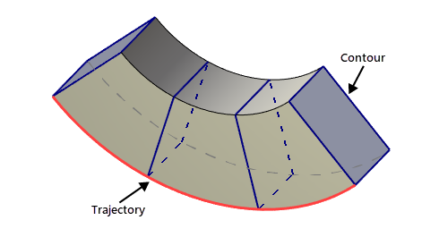
The X-Y plane of the intermediate section coordinate system is always oriented perpendicular to the trajectory. The tangency vector at the point of the section creation defines the Z-axis of the local coordinate system.
This mode is primarily for flat contours. When defining the operation, the plane of a flat contour is always oriented perpendicular to the guiding path in each intermediate point. When using non-flat contours, the system automatically calculates some "mean normal" that is used for orienting the contour.
In case of non-planar contour the system automatically calculates some “mean normal” that is used for orienting the contour. We recommend using additional correction of the original contour position (see section “Correction of Contour Original Position”) in order to get a predictable result.
Parallel to the original profile
The coordinate axes of each intermediate section are oriented parallel to the axes of the original coordinate system. Sweeping in this way results in the parallel translation of the original contour.
By guides
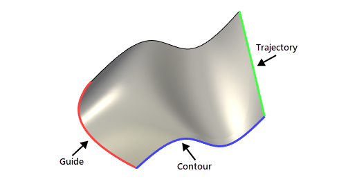
The operation is created by sweeping a contour along the trajectory while orienting the contour towards the points on the additional guides. At the same time, one of the guides also defines the contour scaling law. In this way, the guides are required to be smooth (no corners). This is a special way of creating the operation that will be discussed in a separate topic (Sweep Creation by Guides). In some particular cases faces can be used for defining only orientation (direction) of the intermediate sections.