Create Detail |
  
|
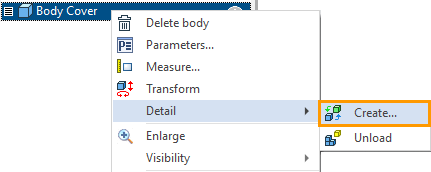
The detail creation dialog can be opened for any body (multiple bodies) or fragment via the context menu.
|
Detail > Create |
The command allows you to create a fragment based on a body (or multiple bodies) in an assembly, and assembly units based on fragments. The command also allows you to open a body or fragment in a separate document.
•You can select a body and place it in a fragment.
•You can select multiple bodies and place them in a fragment. The selected bodies will be moved to the fragment.
•You can select multiple bodies and a single fragment and place them in the fragment. The selected bodies and the selected fragment are transferred to the fragment.
•If you want to put several fragments in a separate fragment in the assembly, i.e. to create a build unit, this action can be performed using the Assembly Structure window: Create Subassembly, or via the context menu: Subassembly > Create (see Assembly unit creation section). The command for assembly units creation will be carried out through the fragment creation dialog.
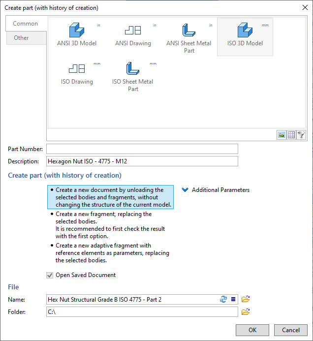
Prototype. The option affects the default commands in the Ribbon and the standard. You can switch commands in the Ribbon.
The Part Number and the Description automatically create a file name on the disk. The principle of creating a file name can be customized. To do this, click the icon ![]() in the Description field and a special Naming Rule dialog appears. Using the icon
in the Description field and a special Naming Rule dialog appears. Using the icon ![]() , you can update the file name according to the selected naming rule.
, you can update the file name according to the selected naming rule.
Create a new document by unloading the selected bodies and fragments, without changing the structure of the current model.
Do Not Save further in the text.
This option allows you to open a body or fragment in a separate document without saving. If necessary, you can save the viewed document with Save command.
Create a new fragment, replacing the selected bodies.
Create Fragment further in the text.
The body to which you applied the Create Fragment command is replaced with a fragment with a separate source file. All body model tree is moved into the fragment file. If necessary, reference element and (or) derived objects will be created (see Reference element section for details).
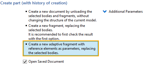
Create a new adaptive fragment with reference elements as parameters, replacing the selected bodies.
Create Adaptive Fragment further in the text.
The body to which we applied the Create Adaptive Fragment command is replaced with a fragment with a separate source file. All body model tree is moved into the fragment file. If reference elements are created during the command execution, they will be added into the geometric parameters of the fragment.
If you create an adaptive fragment (Create Adaptive Fragment) from a body (or bodies), and the body can be completely transferred from the source file to the generated fragment file, reference elements will not be created. Accordingly, the geometric parameters of the fragment will not be created, and the fragment will be non-adaptive.
Any fragment created with the Detail > Create command (both Create Fragment and Create Adaptive Fragment) can then be edited in the context of the assembly and reference elements can be created with the Reference Element command.
Open Saved Document. If the flag is enabled, after selecting Create Fragment or Create Adaptive Fragment, the created fragment will be opened in T-FLEX CAD.
Additional options for creating fragments are available in the drop-down list.
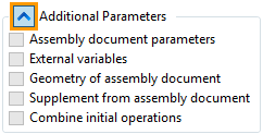
Assembly document parameters. When this option is enabled, all parameters from the assembly document (the document from which the body is placed in the fragment) that are set in the Document Parameters command are passed to the part (the fragment to be created) .
External variables. When this option is enabled, all variables from the assembly file are passed to the part (the created fragment).
Geometry of the assembly document. This option is used for fragments created in the context of an assembly or adaptive fragments. Allows you to unload changes of the geometry on the basis of which a fragment was created in the context of an assembly or adaptive fragment. For example, an adaptive fragment was added to an assembly. If you have added an adaptive fragment and the geometry of its associated features has changed, you can upload the changes to the detail file. If the flag is disabled, the part is created based on the geometry that existed when the adaptive fragment was inserted.
Supplement from assembly document. Allows you to immediately move a fragment or body supplements from the assembly to the detail. For example, a fragment was added to an assembly and a hole was made in it. The supplement option has been activated for this hole. This supplement can be transferred to the part file with the fragment.
Combine initial operations. If a fragment contains several bodies, they can be combined into one body from the assembly. For example, if the bodies of a fragment were supplemented in an assembly in such a way that elements of different bodies were used in the same command, such supplement cannot be transferred to the fragment without combining the bodies.
Example of using the command when working with Top-down assemblies
One of the features of the Detail > Create command is to create a detail based on the bodies in the source file. The source file will become an assembly for the created detail.
Let's continue with the example of Box creation. Let's consider the user has built the body of Box Clip in the file Box Cover. We do not recommend this way, but it is acceptable.
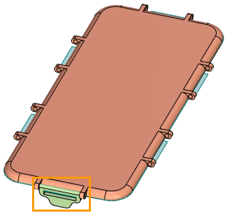
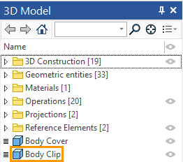
It is necessary that the box Cover fragment contain only one body – Body Cover, and the Body Clip and all related constructions should be in a separate file. In addition, the Body Clip should be a fragment in the Box Cover file.
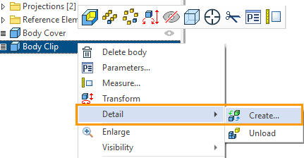
Call the context menu for the Body Clip using ![]() . Select the Create command.
. Select the Create command.
You need to specify Part Number and Description (or fill in only one of the fields). By default, the new file will be saved to the folder where the file in which we use the Create command is located. Select the way to create an adaptive fragment (Create Adaptive Fragment), so that the created fragment of Box Clip is also adaptive (like the fragment of Box Cover) and contains reference elements in the geometric parameters.
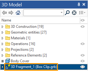
As a result, a fragment appeared in the Assembly Structure window and the 3D Model window of the Box Cover file. The fragment has a Reference Element for those builds that cannot be retrieved from the source file. A fragment of Box Clip has an icon ![]() of adaptive fragment, which has geometric parameters. The geometric Parameters of this fragment can be seen in the corresponding tab of the Assembly Structure window. Automatically created reference elements are added to the geometric parameters, because you have specified the option of an adaptive fragment creation.
of adaptive fragment, which has geometric parameters. The geometric Parameters of this fragment can be seen in the corresponding tab of the Assembly Structure window. Automatically created reference elements are added to the geometric parameters, because you have specified the option of an adaptive fragment creation.
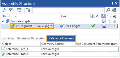
The Geometric Parameters Tab.

When you use the Detail > Create command, the generated fragment relative to the original assembly will always be a fragment of the first level, so its reference elements will always be geometric parameters, in a case that we have chosen the option of creating an adaptive fragment.
In the general case there are several options of how a detail is created on the basis of the body of the assembly.
•Reference Elements will be created (see Automatic Creation of Reference Elements for details).
•Derived objects will be created (see Automatic Creation of Derived objects for details).
•Both Reference Elements and Derived objects will be created.
•Neither Reference Elements nor Derived objects will be created. This will happen if the body can be completely extracted from the assembly.
As you can see in the "Assembly Structure" window of the Box Cover file, after executing the Detail > Create command, the resulting structure is similar to the one we got in the previous case when we used the method of creating a detail in the context of the assembly. However, in this case, the reference element was created automatically.
The ability to receive a detail with automatically created reference elements and fully editable model tree in the detail file, after it was built in the assembly is used to correct the user error, when user creates bodies in the assembly file. Therefore, using the command Detail > Create instead of the command Create 3D Fragment using references is not recommended.
When you save a body in a separate file and rearrange it in the assembly, Reference Elements and (or) Derived objects are automatically created, the number of which and the geometry contained in them we do not control when creating.
When you try to select a complex body from the assembly as an adaptive fragment, recursions may occur that will be eliminated by additional internal Reference Elements or by creating additional subassemblies.
Detailed information about troubleshooting recursions with the help of reference elements you can find out in the section Elimination Recursions Using Reference Elements.
"Top-down" design requires the user to understand the dependencies of the fragments on each other, it is not recommended to use methods to create fragments that complicate the understanding of the relationships in the assembly and complicate the structure of references in the assembly.
The created fragment in the general assembly "Box" became a fragment of the second level. For fragments of the second level (and below) in the Assembly Structure window, you cannot see the geometric parameters, but we can see the reference elements.
If you create a fragment using the command Detail > Create, an update is available for its automatically created reference elements during recalculation. Therefore, the fragments created in this way will update the geometry in the fragment file when you update the references from the Assembly Structure window.
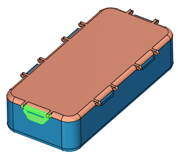
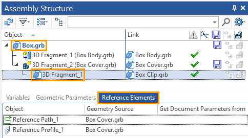
Tab of geometrical parameters.
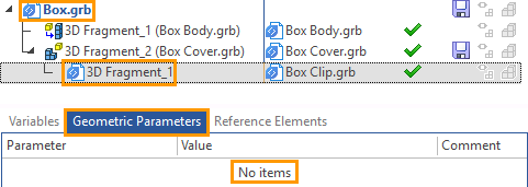
If you make changes to the geometry source reference elements in the assembly "Box" that will change the geometry of the fragment "Box Cover" (because the Cover is a fragment of the first adaptive level for general assembly). The fragment "Box Clip" will also change his position and (or) the geometry, because it is adaptive relative to the assembly "Box Cover".
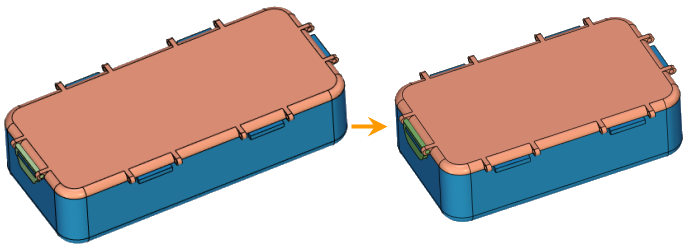
You can create a serial chain of adaptive fragments "Assembly > Fragment of the first level" where each subsequent fragment has a reference element a level higher in the geometric parameters.