Multi-Level 3D Assemblies |
  
|
There are two main ways to create multi-level assemblies.
•Create an assembly structure in the Assembly Structure window by using the Create 3D Fragment command (see Create Assembly Structure in «Assembly Structure» Window) and then work with the selected fragment in the context of the general assembly.
•Create first-level fragment chains by creating and editing fragments only in the context of an assembly at a higher level (see "Two basic ways to create parts in an assembly"). In this way, you can create adaptive fragment assemblies.
Since the example of creating a chain of fragments of the first level were already considered above, now let's consider an example of working with fragments in the context of the assembly at two or more levels above.
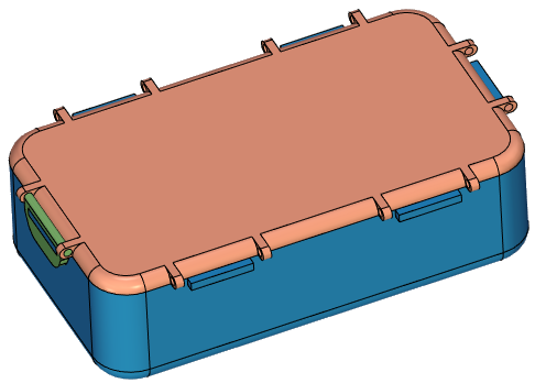
Create a Box Clip in the context of the general Box assembly. We assume that the structure of the assembly, in which the clip is a part of the assembly unit Box Cover is preferable for us, but to create a Box Clip is more convenient for us both on the basis of the faces of Box Cover, and on the basis of the faces of Box Body. Both fragments (Box Body and Box Cover) are available only in the general Box assembly.
Open the previously created Box assembly. The assembly already contains fragments of Box Body and Box Cover, and the fragment of Box Cover is an adaptive fragment of the first level. Create a Box Clip part in the Box Cover subassembly. To create a part in a subassembly, you need to open the context menu of the selection fragment, in which you can select the Create 3D Fragment command. Call the context menu of the Box Cover fragment. Select the Create 3D Fragment command, its dialog window appears. Enter Description: Box Clip, enable the option Edit in Context flag . Editing will be performed in the context of the assembly in which we are at the moment. In our case, the created fragment will be opened in the context of the Box assembly. For the Box assembly, the created fragment is a second-level fragment.
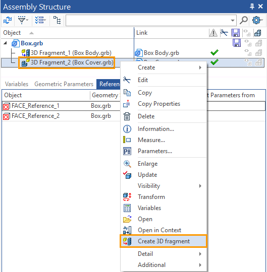
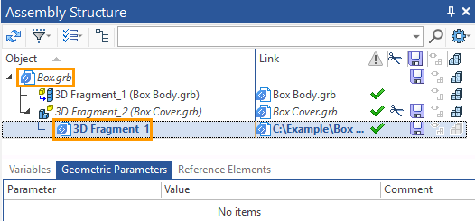
In the Assembly Structure window we can see the resulting structure: the generated fragment is a second-level fragment for the assembly in the context of which we are editing the fragment. The chain of fragments, from the edited fragment to the assembly, is italicized. This way of representation allows you to better understand the position of the edited fragment in the general hierarchy.
Create reference elements. Choose two faces on the Box Cover and the two faces of the Box Body. Two faces on the Box Cover will set the position of the clip axis and its width. The two faces of the Box Body are the dimensions of the groove. That is, you just need to create four reference elements. Reference elements are created using the Reference Element command.
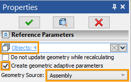
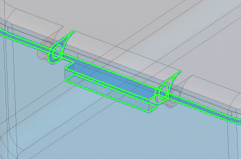
The default settings will be used: specify the creation of geometric adaptive parameters and specify the source of geometry in the assembly file, i.e. the source geometry will be located in the "Box" file. Create links ![]() and exit editing in the context of the assembly with saving
and exit editing in the context of the assembly with saving ![]() .
.
In the Assembly Structure, you can see that the fragment has four reference elements. The file of the source geometry for them is a "Box" file, at the same time, despite the chosen option, the geometric parameters of the reference elements were not included. This is because the assembly part is a second level fragment, and the creation of geometric adaptive parameters is only available for the "Assembly > first-level fragment" relationship.
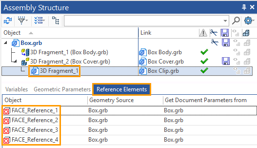
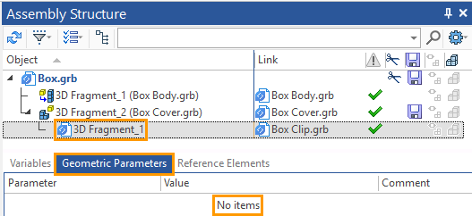
Building a Box Clip on the basis of reference geometry can be done both in the context of the assembly and not. When working in the context of an assembly, it is recommended to disable the Select assembly Elements (the icon ![]() should not be active) option so as not to create random reference elements. After the completion of the constructions creation you should exit the context of an assembly by clicking the icon
should not be active) option so as not to create random reference elements. After the completion of the constructions creation you should exit the context of an assembly by clicking the icon ![]() .
.
If you create the fragment geometry outside the context of the assembly, you should update the assembly after you save the fragment file. In the dialog box that appears automatically when you change the assembly fragments, you should specify the update of the assembly, when you open the assembly file.
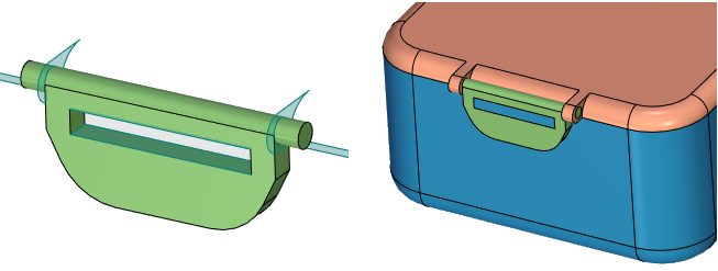
Here is a comparative example of changing the fragments of the first level (containing a reference element in the geometric parameters) and the second level (not containing reference elements in the geometric parameters).
Change, as before, the length of the Box. The length of the Box depends on the length of the Box Body. Decrease the length of the Box Body.
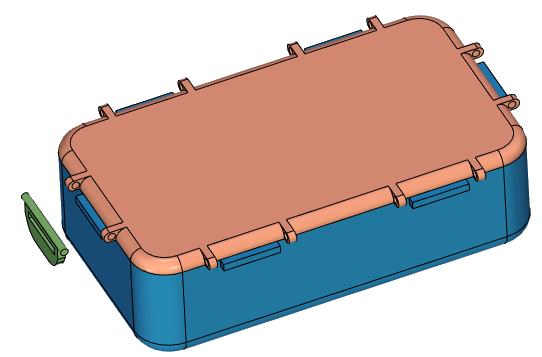
Box Cover is an adaptive fragment and changed its geometry only in the assembly. In the fragment file, the geometry remained unchanged until we update the reference elements. Box Clip is a non-adaptive fragment (without geometric parameters) and remained unchanged. Update the reference elements for the entire model.
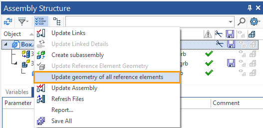
Confirm the update and save. References have been updated. The geometry of the Box Clip has changed in both the assembly and the fragment file. The "Box Cover" fragment file has also changed its geometry.
