Create Three-Face Blend |
  
|
Create Three-Face Blend |
|
Blending can be performed over solid bodies as well as surface bodies. This operation can be considered as a special case of the face-face blend, separated into a dedicated command. Since the three-face blend shares many concepts with the face-face blend, first refer to the Blending faces section for details on certain terms and concepts.
Operation defining steps
The parameters window and the automenu are used for handling the command and defining necessary components. These work simultaneously and enhance each other. The object selection modes can be manipulated via either the automenu or the parameters window.
To create the operation, follow the following steps:
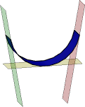
•Select first set of faces (the left wall)
•Select second set of faces (the center wall)
•Select third set of faces (the right wall)
•Set blending type (if necessary)
•Select a guide (if necessary, depending on the type of blending)
•Set result parameters (if necessary)
•Select trim elements (if necessary)
•Set the trim parameters by the walls (if necessary)
•Confirm operation creation
Selecting a set of faces
Normally, the operation definition begins with selecting the sets of faces between which the blend will be constructed. The left and right-wall sets are formed when one of the following automenu options is active:
|
<L> |
Select left-wall face |
|
<C> |
Select center face |
|
<R> |
Select right-wall face |
Switching between the options is done by pressing an icon button in the automenu.
Turning on an option automatically activates the respective tab on the parameters window. The list of selected faces of the right or left wall is displayed in the provided pane under the tab tag. Switching between the tabs of the parameters window also activates the appropriate options for face selection.
Face selection is done using the mouse in the 3D view window. The current face highlighting color is indicated by the colored box on the tab tag for each set.

To automatically select a linked sequence of smoothly conjugate faces, you need to enable the option:
|
<S> |
Smooth face chain selection mode |
After enabling this option, it is enough to specify any face of the required wall that is included into the required sequence. The remaining faces will be added automatically.
You can deselect all items at once using the option:
|
<K> |
Cancel selection |
A decorator is drawn in the middle of each face, shaped as an arrow, marking the side of the face adjacent to the blend surface. The blend is created on the side pointed at by all three arrows.


Control over the arrow directions is done via the Orientation drop-down list right of the face list pane on each tab in the parameters window. Selection is made in the pull-down list. For solid bodies, the direction of an arrow is determined automatically. In this case, the Auto option is set for all faces. For surface bodies, the direction of faces has to be controlled manually by the user.

To change the system default arrow direction, select one of the other two available orientation settings, Normal or Reverse.
To exclude a face from the wall set, simply select it in the list in the parameters window on the respective tab and press Delete button.
To ensure the participation of adjacent edges of the middle wall conjugated at an angle in the blending creation, it is necessary to set the flag in the Propagate field in the corresponding tab of the parameters window and set the maximum conjugation angle of these faces.
![]()
Choice of Blending Form
The selection of the type of blending is carried out using the corresponding icons in the parameters window. By default, the system sets the spherical type of blending.

Spine Selection
To turn on the spine selection mode, activate the following automenu option.
![]() <W> Select guide spine
<W> Select guide spine
Selection of a 3D path is done in the 3D window or in the model tree by the mouse. The name of the selected 3D path is displayed in the Guide Spine box of the parameters window.
![]()
Setting Result Parameters
Multiple Solution
The selection of an auxiliary point to refine the result in the case of the formation of several blending surfaces is performed after the Multiple Solution checkbox is enabled in the parameters window.

To do this, activate the corresponding field and select the desired 3D point in the 3D window. The selection of the auxiliary point is canceled using the button ![]() .
.
Select Type of Walls Trimming
The selection of the type of wall trimming is carried out using the corresponding buttons in the parameters window. By default, the system sets the type to Auto.

To create a blending surface in the form of a separate body, you should enable the Single body checkbox in the parameters window.
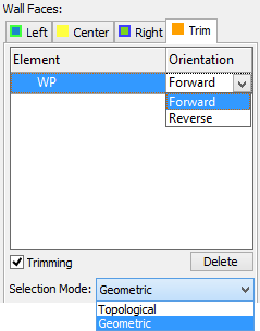
Selection of Trim Elements
To select the elements that limit the blending zone, it is necessary to use the Trimming tab in the parameters window. Then determine the mode of selecting items: topological (faces, cycles, edges) or geometric (planes, surfaces, straight lines).
Elements are selected using the mouse in the 3D window after activating the Element field.
The direction of the resulting blending surface is determined by the value of the Orientation drop-down list.
To delete a bounding element, simply select it in the list of the parameters window and click the Delete button.
The Trimming checkbox allows you to determine the position of the blending boundary relative to the guide.
Trimming by Walls
The way to trim the edges of the blending surface is selected from the drop-down list of the Trimming by Walls option in the parameters window. By default, the system sets the By Both Walls trimming method.
In order for the middle wall not to be taken into account when creating the blending surface, it is necessary to enable the Ignore Middle Wall checkbox.
