Filling a 3D Assembly with Geometry |
  
|
Filling a 3D Assembly with Geometry |
|
As mentioned above, when working with assemblies "Top-down", design is performed from an assembly to its parts. The part geometry is defined by a set of parts included into the assembly. That is, the geometry of some parts is determined by others, taking into account their position in the assembly. As a rule, there are parts or subassemblies that do not depend on other parts – these are parts of large frameworks, various cases, frames, fuselages, etc. This details should be created first. They will fill the assembly with geometry, on the basis of which it will be possible to design from assembly to parts.
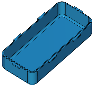
Consider a simple example. You should design a Box, the geometry of the Box Body is determined by the required volume, dimensions, wall thickness and method of the cover fixing. Box Body defines all other parts of the assembly, while other parts do not affect the geometry of the Box Body, respectively, the design of the Box should start with the "Box Body" part. Create an assembly, which is a fragment of the Box Body. There are two ways to do this.
•Create a new document from 3D Model prototype and build a Box Body, then create another document of the 3D Model prototype (Box file) and set the fragment Box Body into an assembly Box using the command 3D Insert Fragment.
•Create a new document from the 3D Model prototype, then use Create 3D Fragment command to create a new fragment, and then create a box Body in the context of the assembly or not in the context of the assembly (in this case it does not matter, because Box Body does not depend on other constructions). Before you create a case, you can create the entire Box assembly structure at once.
The first method corresponds to "Bottom-up" principle of design, the second to "Top-down" principle. In this case, both the first and the second way will lead us to exactly the same result. In General, when you create assemblies, you can apply both design principles at the same time.
Let's use the second method. Create an assembly file. Save it and call it "Box". Select command Create 3D Fragment. In the appeared dialog box, enter the description of the part, or Part Number, or both. Working with the fragment creation dialog is described in the Create 3D Fragment section. Select the 3D Model prototype. The Edit in Context flag can be omitted, because there are no other bodies in the assembly at the moment and there is no need to create reference elements for the body.
After clicking OK you are still in the "Box Body" file. In the Assembly Structure window is shown that a fragment has appeared in the assembly. Its icon ![]() indicates that the fragment is not adaptive. To edit a fragment, open its context menu and select Open. In the file there are no constructions, the coordinate system of the file coincides with the coordinate system of the assembly. Create a body Box Body on the basis of the primitives or by creating the required standard workplanes.
indicates that the fragment is not adaptive. To edit a fragment, open its context menu and select Open. In the file there are no constructions, the coordinate system of the file coincides with the coordinate system of the assembly. Create a body Box Body on the basis of the primitives or by creating the required standard workplanes.