Unload Detail |
  
|
Unload Detail |
|
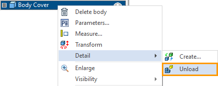
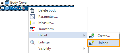
The dialog of the detail unloading command can be called for any single body or a single fragment via the context menu.
|
Detail > Unload |
There are four options for unloading are available in the dialog.
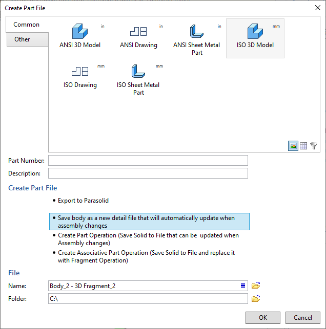
The first option of unloading allows you to save the body in the Parasolid format.
The first and second options of unloading are described in the section Save geometry from assembly in separate file.
The third and fourth options of unloading are described in this section.
The resulting part is included into product composition, only when using third or fourth unloading option.
The Part Number and the Description automatically create a file name on the disk. The principle of creating a file name can be customized. To do this, click the icon ![]() in the Description field and a special Naming Rule dialog appears. Using the icon
in the Description field and a special Naming Rule dialog appears. Using the icon ![]() , you can update the file name according to the selected naming rule.
, you can update the file name according to the selected naming rule.
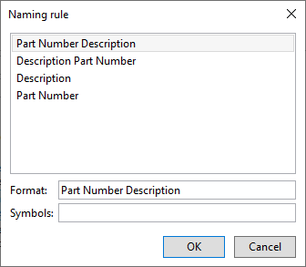
By default, the file is saved to the folder where the file is located from which the upload is made.
Upload the geometry with the possibility of subsequent updates
If the body was created in an assembly (subassembly of any level), you can unload it by making a part. To do this, select the Detail command in the context menu of the body. You should select the third or fourth option of the body unload in the Detail > Unload command, for a fragment to be created as a fragment with a geometric parameters, but without reference elements
•Unload a detail (the Detail > Unload command) with the option Create Part Operation (Save Solid to File that can be updated when assembly changes).
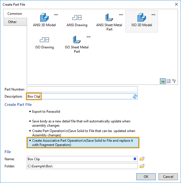
•Unload part (the Detail > Unload command) with the Create Associative Part Operation (Save Solid to File and replace it with Fragment Operation) option.
The build tree is not available in the fragment files created by the third or fourth variant of the Unload command. The geometry in the files is an external model. You can edit the geometry of the fragments only when you change the geometry of the body in the assembly file. The possibility to edit fragment files after they are created on the basis of bodies in the assembly is given by the Detail > Create command.
It is rational to apply the options for the creation of fragments in the assembly described in this subsection in the case, when unloading the body using the command Detail > Create leads to recursions (more information about recursions and their removing can be found in the section Elimination Recursions Using Reference Elements). The other case is when you want to make a part dependent on an assembly without using reference elements.
The two ways for creating fragments are not recommended if the fragments you are creating are subassemblies.
Create Part Operation
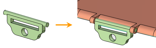
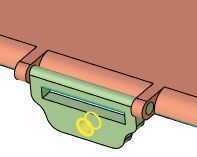
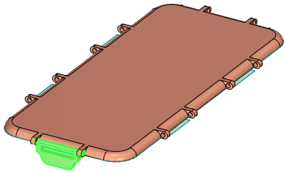
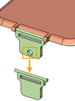
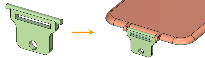
Again consider the example, when we designed the Box Clip in the Box Cover file fragment and want to create a fragment based on Box Clip body (this example was already discussed in the section Create Detail).
Call the context menu of the Body Clip body and select the command Detail > Unload.
In the appeared dialog, specify the Create Part Operation (Save Solid to File that can be updated when assembly changes) option. The principle of entering the name of the file and the choice of the prototype is similar to the principle when working with dialog of fragment creation. In the beginning of this section you can see a brief information about this dialog.
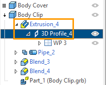
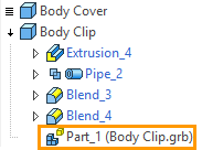
As a result of the command, an adaptive fragment will appear. In the 3D Model window you can see that an adaptive fragment appeared in the Body Clip body structure.
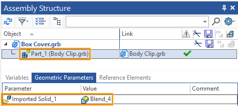
A fragment of the first level also appeared in the Assembly Structure window of the "Box Cover" file. This fragment contains geometric parameter "Imported Solid_1" and does not contain reference elements.
The Reference Elements Tab.
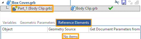
The presence of the "Imported Solid_1" geometric parameter provides the link of the "Box Clip" fragment file with the "Box Cover" assembly, i.e. the link with the file from which the geometry was unloaded. You can transfer changes made to the source body in the assembly file to the fragment file. To do this, select the Update command.
Only changes made for operations, which are located in the body tree before unloading, and changes made in the fragment supplement mode will be transferred to the fragment file.
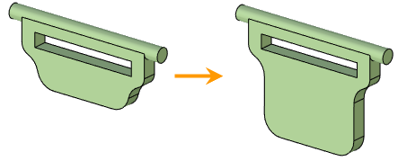
For example, we can change the length of the Box Clip by changing the profile of the extrusion operation, which is located before unloading. After changing the geometry of the clip body, call the Update command via the context menu.
|
|
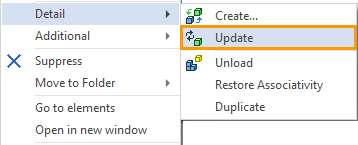
After executing the Update command, the fragment file will be updated according to the body changes in the assembly and saved.
You cannot transfer changes in the geometry of the body, performed due to operations that are in the body tree after unloading, to the fragment file. For example, if we make a hole in the Body Clip and the operation is located after unloading, the Update command will not pass the changes to the fragment file.
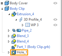
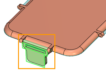
We can add operations in an unloaded tree of the body. To do this, call the context menu of the last operation of the body and select the Rollback Model command. Call a rollback command for the Body Clip.
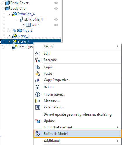
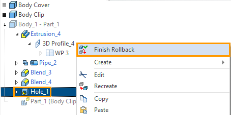
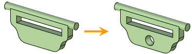
Add a hole to the Box Clip geometry. As you can see from the picture, hole was added to the tree of body operations. To finish editing the body, you need to call the context menu for body operations or call the context menu in the free space of the 3D scene, and select Finish Rollback.
|
|
A hole created in this way can be passed to the fragment. To do this, select the Detail > Update command in the context menu of the clip body. The fragment file will be updated, modified according to the assembly, and saved.
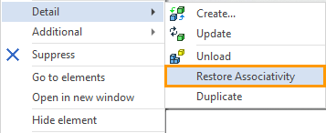
We can pass the changes made in the fragment to the assembly. To do this, use the command Detail > Restore Associativity.
Make a hole in the Box Clip, not in the assembly, but in the fragment file. To do this, open the Box Clip fragment file and make a hole in it, then save the fragment file. In the "Box Cover" assembly, call the command Detail > Restore Associativity in the context menu of the Body Clip body.
As a result of the operation, the changes made in the fragment will be transferred to the assembly.
The Detail > Restore Associativity command will be available in the context menu only if changes have been made to the fragment file.
Create Associative Part Operation
Consider the fourth option to unload Create Associative Part Operation (Save Solid to File and replace it with Fragment Operation).
As in the previous case, call the command Unload through the context menu of the Body Clip body in the assembly, but this time specify the fourth option.
Displaying the created fragment in the 3D Model and Assembly Structure windows is similar to the previous variant of unloading.
As in the previous case, the fragment has no reference elements and has a geometric parameter ("Imported Solid_1"). The Geometric parameter connects the fragment with the assembly.
As in the previous case, the generated fragment has a link only to the assembly file from which it was unloaded.
As in the previous case, we can make changes to the body operations that were created before the unload and then use the Update command to upload them to the fragment file.
As in the previous case, we can add operations to the body tree before unloading – using the Rollback Model command.
Unlike the previous unload option, changes made to the fragment will be automatically transferred to the assembly. That is, to update the assembly according to the changes in the fragment file, we do not need to use the command Detail > Restore Associativity.
Make changes to the clip fragment: create a hole, then save the fragment. If you open the file "Box Cover" then, as in the case of changing all the fragments, you will be asked about updating the assembly. After the update is confirmed, the fragment in the assembly will be updated.