Saving Geometry from 3D Assembly to Separate File |
  
|
To create drawings of details that have different variations in the assembly, it is convenient to save the part to a separate file. Detail models saved from an assembly to a separate file can be transferred to other users who, for some reason, do not need to work with the entire assembly. Therefore, a mechanism by which the bodies or fragments that go into the assembly can be saved to a separate file was implemented. The file can be updated according to changes in the assembly, but the changes made in the file will not be transferred to the assembly.
•The Detail > Unload command with the option Save body as a new detail file that will automatically update when assembly changes.
•The Detail > Unload command with the option Export to Parasolid.
•The Detail > Create command without creating fragments (first option).
In case of changes in the assembly, a file in the Parasolid format should be saved again. Consider these options to save the geometry in a separate file.
If there were drawings in the fragment that was saved as a separate file, they will be changed according to the changes in the fragment in the assembly.
Save Geometry with Update Possibility
In cases when you want to save a particular variation of a body or a fragment (for fragments with External Variables or Geometric Parameters) in a separate file, for example, to create a drawing, or transfer to another user, you need to use the Detail > Unload command with the option Save body as a new detail file that will automatically update when assembly changes. If you use this command, the model constructions tree will not be available to the user.
Suppose you have a Housing assembly (file "Housing.grb") in which there is only one fragment of the Housing Base. The fragment has no reference elements and no geometric parameters, i.e. it is non-adaptive and is created in the assembly using the Create 3D Fragment command.
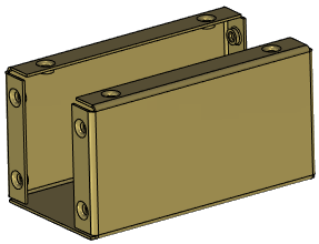
Let's say that you started to create a cover in the assembly. The side cover should be unloaded to a separate file and the changes from the body should be transferred to the file. At the same time, you do not need to create a correct assembly structure and reinsert the saved body as a fragment.
|
|
In the 3D Model window, call the context menu for the Side Cover body and choose the Detail > Unload command .
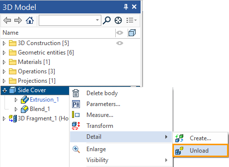
In the dialog that appears, select the Save body as a new detail file that will automatically update when assembly changes option. A brief description of the dialog box can be found in the Unload Geometry with Possibility of Subsequent Updates section. As a result of the operation, a "Side Cover" file was created.grb", and a related item appeared in the constructions tree (in the Linked details folder). The command did not affect the assembly structure, and there will be no changes in the Assembly Structure window. You can make multiple separate files for a single body.
You can place the generated file as a fragment in an assembly by using the Insert 3D Fragment command.
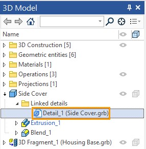
Insert the "Side Cover.grb" file into the assembly. A new fragment appeared in the 3D Model and Assembly Structure windows.
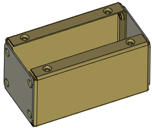
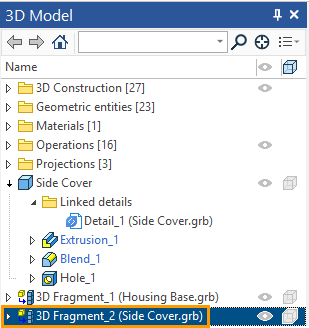
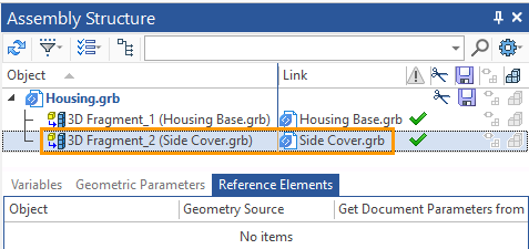
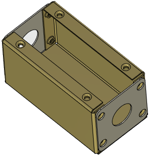
Make changes to the Side Cover body and add a hole.
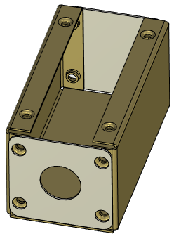
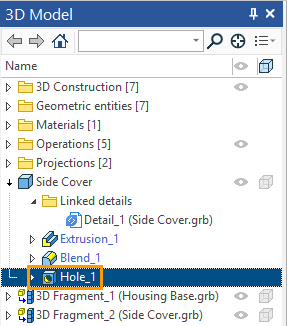
To upload changes to the "Side Cover.grb " file you need to use a special command.
Icon |
Ribbon |
|---|---|
|
- |
Keyboard |
Textual Menu |
- |
File > Assembly > Update Linked Details |
You can call the Update command Linked Details in the Assembly Structure window through the Actions menu (see the section Assembly Structure window).
You can update a specific detail by calling the context menu for the linked detail. In this case, there will be no difference because there is one detail.
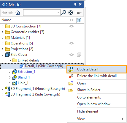
The command adds a hole to the part file, and if you update the assembly, the "Side Cover" fragment also changes its geometry.
Other context menu commands.
Delete the link with detail. Allows to break the link to the uploaded detail: the detail is no longer associated with the assembly and cannot be updated.
Open. Opens the detail file.
Show in Folder. Show the detail file in Windows Explorer.
The Update Linked Details command is also available in the context menu. It allows you to update details for selected objects.
Maintain Variation of Parametric Fragment Geometry
Another important feature of the Detail > Unload command with the Save body as a new detail file that will automatically update when assembly changes option is the ability to unload different variations of parametric fragments, i.e. fragments with External Variables and (or) Geometric Parameters.
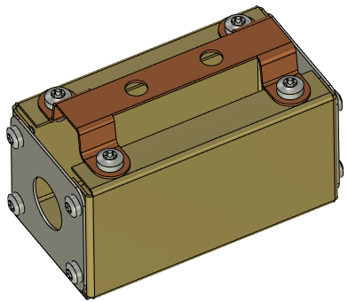
Let's go back to the Housing example. Side Covers are connected with the Housing Base by means of screws D4хL6 and with Bracing by means of screws D5хL8.
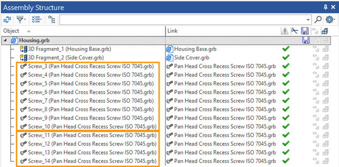
From the Assembly Structure window, you can see that different screw versions (D4xL6 and D5xl8) refer to the same file. I.e. a fragment of the screw is parametric (contains External Variables) and allows to implement all possible variations according to the standard.
If you need to fix some specific variations of parametric fragments (for example, to create a drawing), you need to create a separate file with one or another variation of the parametric fragment. However, you don't need feedback to this file, but we need to be able to pass changes to the file if the variation of the fragment in the assembly has changed. Using the Detail > Unload command, create two files associated with the assembly: the first with the D4хL6 variation and the second with the D5хL8 variation.
In the 3D Model window or in the Assembly Structure window, call the context menu for the D5xL8 screw fragment. In the context menu, select the Detail > Unload command. Specify the Save body as a new detail file that will automatically update when assembly changes option in the dialog box . Call the file so that its variation is clear.
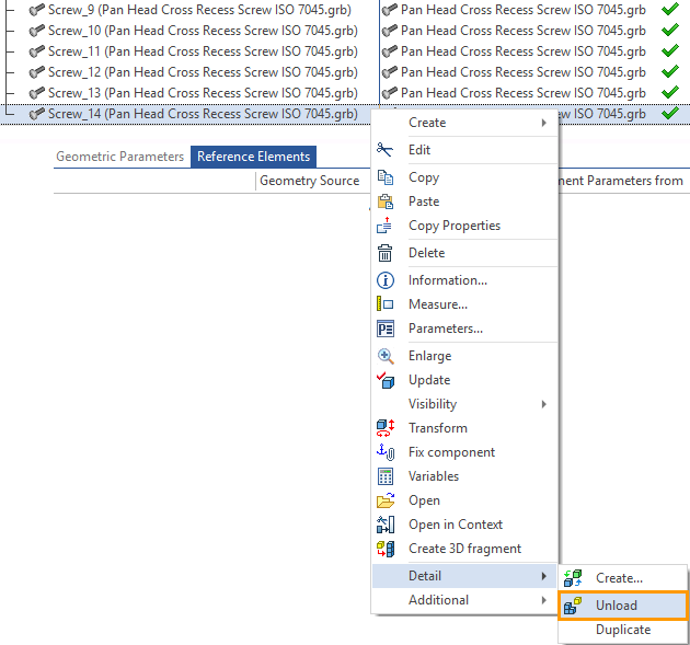
As a result "Screw D5хL8.grb" file was created. This action does not appear in the Assembly Structure window.
In the 3D Model window, you can see the created file in the Linked details folder. As in the case described above, when the command Detail > Unload (with the option of unloading) was applied to the body in the assembly, you have the opportunity to transfer the geometry changes from the assembly to the created file.
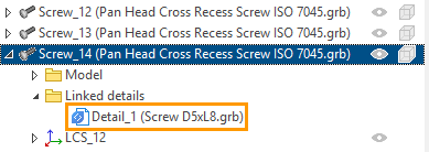
To update the geometry of the "Screw D5хL8.grb" file, according to the changes of the fragment in the assembly, you need to use the Update Linked Details command, or in the "3D model" window through the context menu of the related part to call the update command for a specific file.
You can create a file with the variation of the screw D4xL6 in the same way.
Save Geometry in Parasolid Format
When you select the first item in the dialog of detail unload: "Export to Parasolid" a dialog for exporting part to Parasolid appears. The selected items are saved in a separate Parasolid file (*.x_t). The file does not depend on the assembly. The export operation has no effect on the assembly model structure.
Save Document View
If necessary, you can save a document that is opened after execution of the Detail > Create command with the Do Not Save option. For this, open document and execute the Save command.
Such actions are required in the case, when you need a model tree in the file of the geometry, saved from the assembly. At the same time, the link of such a file with the assembly should be controlled manually. if reference elements are automatically created when you run the Detail > Create command, they should be updated in the created file if the assembly changes. You can insert the generated file as a fragment in assemblies by using the Insert 3D Fragment command.
Let's continue with the example of the Housing assembly. Let's say you need to save the Bracing body that was created in the Housing assembly, as a separate file. It should be possible to work with the constructions tree of the body. In this case, the assembly does not need the changes made in the file, but you need to transfer the changes made in the assembly for the detail file. This is necessary, for example, when Bracing has different versions. Then, to create a drawing of the second version of Bracing, you will have a 3D model in which, due to the available model tree, you can make the required changes. The Bracing 3D model has a link with the assembly by means of the reference elements. In case of changes, Bracing will receive the actual geometry when updating the reference elements. You can create as many separate 3D models of a single body or fragment as you want.
Call the context menu for the Bracing body in the 3D Model window. Select the command Detail > Create. This dialog box was described above. Select the Do Not Save option.
Enter Description: "Bracing". As a result, the "Bracing.grb" file was created.
There will be no changes in the 3D Model and Assembly Structure windows of the Housing assembly file.
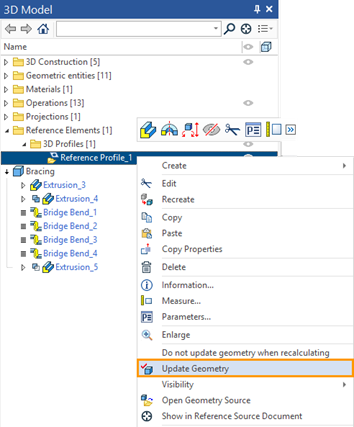
A model tree is available in the file "Bracing.grb". A reference element for the profile, which parent elements cannot be taken from the assembly, was automatically created. The profile depends on the assembly and will link the model to the assembly by means of the reference element. To update the reference geometry, call the Update Geometry command from the context menu of the reference element.
|
|
You can edit the constructions and create a new variation of the detail. For example, edit the constructions that define the profile and change the number of holes.
|
|
You can create separate documents not only for bodies, but also for fragments. At the same time, when you save the fragment document, the constructions tree will also be available. In this case, you create a copy of the fragment file, but only in the variation in which the fragment is in the assembly.
Save the "Box Cover" fragment from the "Box" assembly into a separate file.
The "Box Cover" fragment has reference elements.
|
|
In the 3D Model or Assembly Structure window call the context menu for the fragment "Box Cover", choose the command Detail > Create, and select the first option. View the opened document of the Box Cover fragment. If the document fragment was opened correctly, save it. As a result, a separate file is created in which the 3D model Box Cover is located. The whole constructions tree is available for the model. The reference elements of the fragment were also saved. They can be updated to get the latest geometry from the assembly.
|
|