Direction, Fixed and Tapered Elements of Face Taper |
  
|
Taper Direction
The direction, in which the taper (slant) angle of the faces is counted, is determined by a vector. This vector can be defined in two ways.
•The first way requires selecting an object, whose geometry will determine the taper direction: a normal to a face, a flat edge, etc.
•Alternatively, the vector can be defined by two 3D points. The second 3D point defines the vector direction.
When designing parts made by parts made by molding, it is necessary to specify the direction of the taper along the direction of the mold separation.
Specifying taper direction
For specifying a taper direction by one 3D object, the following option is used:
|
<D> |
Select tapering direction |
This option allows selecting objects in the scene, whose geometry is suitable for defining the taper direction vector. Once an object is selected, its name appears in the parameters window.
![]()
For defining a taper direction by two 3D points, the following options are used:
|
<1> |
Select first point of tapering direction |
|
<2> |
Select second point of tapering direction |
The selected elements are also entered in the parameters window. The taper direction is marked by a vector in the 3D scene.

To cancel the direction selection, use the option:
|
<X> |
Cancel direction selection |
Fixed Edge/Fixed Taper Face
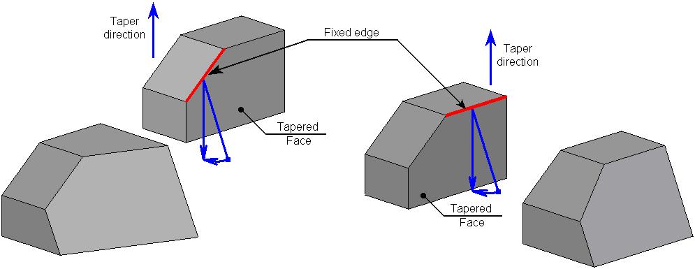
For each tapered face, it is required to specify a fixed edge or a face.
A fixed edge defines a fixed taper line – a line, lying on a tapered face, which does not change its position when creating a taper. Construction of a taper surface takes place with respect to a fixed line. A fixed edge must belong to the same body as a tapered face.

Instead of an edge, it is possible to indicate a fixed face. Intersection of the selected face with the tapered face defines a fixed taper line.
Unlike the fixed edge, the fixed face can be selected on a different body. Once the fixed face is selected, the command creates the plane based on that face, and projects it to the intersection with the face to taper. The intersection line between this line and the face being tapered is the fixed line about which the face tapering will occur.

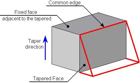
A fixed face can be adjacent to the tapered face. In this case the common edge will be a fixed edge with respect to which the face will be tapered.

Fixed edges and fixed faces are defined separately for each tapered face.
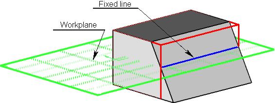
Instead of collection of fixed edges, it is possible to specify one workplane. It will define a fixed line for all tapered faces of the current operation at once. A fixed line of each tapered face will be defined as an intersection of selected workplane with the given face.

Specifying Fixed Object and Tapered Face
After defining a taper direction, the command will prompt you to define a fixed line of the first tapered face. The following automenu options are used for that:
|
<T> |
Select fixed Face |
|
<E> |
Select fixed Edge |
|
<W> |
Select Workplane |

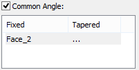
After selecting the respective element, it will be added to the list Fixed/Tapered of the command’s parameters window.
Then the system will prompt you to select a tapered face. The following option will become active in the automenu:
|
<F> |
Select faces to be tapered |
Selected tapered face is also added to the list Fixed/Tapered next to the corresponding to it fixed object.
A fixed line (edge, face, workplane) and a tapered face are specified in pairs. Each tapered face must correspond to a fixed object, and vice versa.

Further action of the command depends on the type of the selected fixed object. If it was a fixed edge, then the system will prompt you to select the next fixed edge. If it was a face or a workplane, the system will wait for specification of one more tapered face. Selected earlier face/plane will be, by default, considered as a fixed object for all subsequently selected tapered faces. To select another fixed object, it is necessary to manually activate the corresponding option (![]() or
or ![]() ), select a desired object (face or edge), and then specify a tapered face.
), select a desired object (face or edge), and then specify a tapered face.
Note that in the framework of a single operation, it is possible to specify only one workplane – it will become a fixed object for all tapered faces.
For creating the taper of all faces adjacent to a single fixed edge, it is sufficient, after selection of the fixed edge, turn on the following automenu option:
|
<A> |
Select all adjacent faces for tapering |
All faces adjacent to a specified fixed face will be automatically selected as tapered.
To modify already selected fixed objects or tapered faces, it is necessary to select a desired pair in the list Fixed /Tapered, turn on the option of selecting a desired object (![]() ,
,![]() or
or ![]() ) and select an object again.
) and select an object again.
It is possible to delete a specified pair fixed object/tapered face by selecting them in a list, pressing key <Del>.
It is also possible to cancel selection of the workplane with the help of the option:
|
<X> |
Cancel workplane selection |