Value of Face Taper |
  
|
Calculating taper angle
Taper angle of face can be evaluated according to the following algorithm:
•A normal to the face to taper is constructed at each point of the fixed edge.
•The taper direction vector is translated to that point.
•Based on those two vectors, a plane is constructed, in which the taper angle will be counted.
•Next, the vector is determined, that sets the zero taper angle.
The taper angle is counted from the formerly described vector in the plane. This angle defines the resulting vector, through which the surface of the tapered face will be passing.
|
|
1 - Tapered face 2 - Current taper angle 3 - Manipulator arrow marking zero taper position 4 - Taper angle is measured in this plane 5 - Direction defined by two 3D nodes 6 - Fixed edge 7 - Taper direction vector 8 - Normal vector to the tapered face is constructed |
Resulting face taper |
Setting taper angle
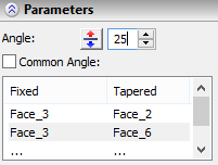
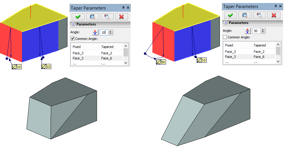
The taper angle is defined by a numerical value in the operation parameters. It can be common across the whole set of pairs of fixed objects and tapered faces, or be defined individually for each pair. By default, the common angle is used.

If for a certain pair fixed object/tapered face, it is desired to define a value of the angle different from the common, it is necessary to perform the following steps:
•In the parameters window, click the desired pair of the fixed and tapered objects.
•Clear the check mark on the option Common Angle.
•Specify the angle value for the selected pair.
The command provides manipulators for easy setting of the face taper angles. By using the manipulators, you can dynamically modify the taper angle value.
In certain cases the manipulators may not be displayed.
A manipulator for defining face taper angles appears as two vectors connected by an arc. Both vectors originate from the fixed object (a face or an edge). The direction of the first vector coincides with the taper direction. The direction of the second vector defines the resulting position of the tapered face. The taper angle is set by dragging the tip of the second vector.
A separate manipulator is provided for each pair fixed object/tapered face in the 3D scene. If a common angle is used for all pairs fixed object/tapered face, then you can modify the taper angle by any of the manipulators. If the “Common angle” option is turned off for any of the pairs, then the manipulator position will affect the angle of this pair only.

To change the face taper direction, either enter a negative angle value or push the ![]() button in the face taper parameters dialog.
button in the face taper parameters dialog.
Creating Taper by Offset
For creating face taper by offset it is required:
1.Specify a taper direction;
2.Indicate a fixed taper line;
3.Indicate a tapered face or a collection of faces;
4.Select a face in the plane of which the offset will be created;
5.Specify the offset of the tapered face;
6.If necessary, define additional parameters (the method of filling the junctures between the tapered and non-tapered faces, between faces tapered at different angles, etc.);
7.Complete operation creation with the help of ![]() .
.
Taper direction, fixed taper line and tapered face are specified in the same way as for the standard taper. For specifying the face in the plane of which the offset will be created, it is necessary to turn on the following automenu option:
|
<O> |
Select Face for creating taper by offset |

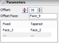
The name of the selected face will be displayed in the command’s parameters window (the field Offset face). The offset is specified as a numeric value of the parameter Offset.
When specifying the face for defining the offset, the parameter Method is automatically assigned to the value Taper by offset.