Methods of Creating Worksurfaces |
  
|
There are three methods to create a worksurface:
1. Creating a worksurface by an existing geometrical surface of the respective type (a surface underlying a face, 3D profile, another worksurface). This method was used in the aboveDescribed examples.
2. Creating an arbitrary worksurface (that is, without being based on existing geometrical surfaces in the 3D model) in the 3D window.
3. Creating an arbitrary worksurface based on 2D constructions (in the 2D window).
Worksurface based on existing geometrical surface
Worksurface creation by an existing geometrical surface is performed in the 3D window. To define the source data, select a 3D object related to the intended geometrical surface. As a result, a worksurface is created that coincides with the source geometrical surface.
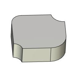
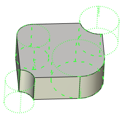
Additionally, you can specify an offset amount (two offsets for a torus), which defines the difference between the source and target surface radii. In this case, a worksurface will be created as an equidistant (offset) to the source geometrical surface.
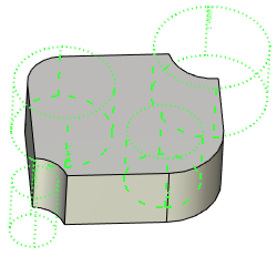
The source geometrical surface coordinate system is used as the Cartesian coordinate system for the created worksurface. The coordinate system position for the worksurface being created can be adjusted by selecting an additional 3D point - starting point. The starting point will determine the worksurface coordinate system origin (that is, the X-axis direction of the Cartesian coordinate system). Two 3D points are defined for a spherical worksurface – starting point and pole; first determining the X-axis direction, and the second adjusting the Z direction (and, therefore, the Y-axis).
|
|
Cylindrical worksurface |
Similar cylindrical worksurface |
A separate 2D page of the “Workplane” type is automatically created for a constructed worksurface. The page's format frame size is determined automatically by the size of the 3D object that was used to define the source geometrical surface. The parametric 2D region of the worksurface is also created automatically. Its size is equal to the size of the page format frame.
The created worksurface is by default displayed in the 3D window.
Arbitrary Worksurface
An arbitrary worksurface is also created in the 3D window. To create a worksurface by this method, you need to specify the type and the radius (two radii for a torus) of the surface being created.
Additionally, you can specify an LCS, relative to which the parametric coordinates of the worksurface will be counted.
As in the previous method, a separate 2D page of the “Workplane” type is automatically created for such worksurface. The dimensions of the page format frame and the parametric 2D region worksurface are automatically determined by the system.
Worksurfaces of this type are also displayed in the 3D window by default.
Worksurface based on 2D constructions (in 2D window)
Creation of a worksurface of this type is done in the 2D window, on an already existing drawing page of any type. To create the surface, you need to define the boundaries (two diagonal corners) of its parametric 2D region. The region boundaries are defined using two 2D nodes. The position and the order of selecting the 2D nodes determine the direction of parametric axes of the worksurface. Besides that, the radius is to be defined (two radii for a torus) of the surface being created.
Additionally, you can specify an LCS, relative to which the parametric coordinates of the worksurface will be counted.
A worksurface of this type can be created on a 2D page that is already related with other worksurfaces or planes. In this case, the boundaries of the parametric 2D region are used by the system to automatically match the 2D elements found on this page, with the respective worksurface/plane (when creating 3D elements – 3D profiles, 3D paths).
If several worksurfaces/planes are related to a 2D drawing page, those cannot be activated.
Rules of creating worksurfaces
Upon calling the command, the following options are available in the automenu:
|
<S> |
Select Face |
|
<1> |
Spherical coordinate system |
|
<2> |
Cylindrical coordinate system |
|
<3> |
Ring-shaped coordinate system |
The first option – ![]() – serves to construct a worksurface by an existing geometrical surface.
– serves to construct a worksurface by an existing geometrical surface.
The other three options – ![]() ,
, ![]() and
and ![]() – are used to construct either an arbitrary worksurface in the 3D window or a worksurface based on 2D constructions (in the 2D window). How a worksurface will be created depends on where the command call originated – from the 3D window or from the 2D window.
– are used to construct either an arbitrary worksurface in the 3D window or a worksurface based on 2D constructions (in the 2D window). How a worksurface will be created depends on where the command call originated – from the 3D window or from the 2D window.
These options are also available as separate commands:
Icon |
Ribbon |
|---|---|
|
Support Geometry > Worksurfaces > Spherical Surface |
Keyboard |
Textual Menu |
<3SV> |
|
Icon |
Ribbon |
|---|---|
|
Support Geometry > Worksurfaces > Cylindrical Surface |
Keyboard |
Textual Menu |
<3SB> |
|
Icon |
Ribbon |
|---|---|
|
Support Geometry > Worksurfaces > Toroidal Surface |
Keyboard |
Textual Menu |
<3SN> |
|
Creating worksurface by an existing geometrical surface
To create a worksurface by an existing geometrical surface, use the option ![]() . It is turned On by default. With the option enabled, select a 3D object in the 3D window or in the model tree, suitable to define a surface of the cylindrical, spherical or toroidal type. This could be a face of the respective type, a 3D profile, or an existing worksurface.
. It is turned On by default. With the option enabled, select a 3D object in the 3D window or in the model tree, suitable to define a surface of the cylindrical, spherical or toroidal type. This could be a face of the respective type, a 3D profile, or an existing worksurface.
After selecting the source 3D object, the system will automatically determine what-type worksurface will be created. The command's parameters window will have the dialog to define parameters of the given worksurface. Depending on the type of the created worksurface, you can define the values of one or two offsets in the parameters window. The offsets determine the difference between the radius of the source geometrical surface and the radius of the worksurface being created.
Original direction of worksurface coordinate axes corresponds to direction of the parent surface. Reverse Direction flag in the parameters window will reverse direction of both axes.
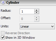
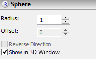
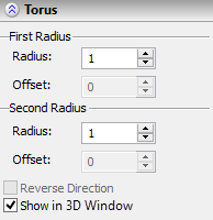
Additionally, the option is available in the automenu to select a 3D point defining the worksurface coordinate origin:
|
<1> |
Select starting point |
|
<2> |
Select Pole point |
|
<D> |
Cancel selection of points setting surface orientation |
Creating an arbitrary worksurface (in the 3D window)
To create a worksurface of this type, you must call the command Construct Worksurface from the 3D window. After entering the command, you need to specify the type of the surface being created, by selecting the desired automenu option (![]() ,
, ![]() and
and ![]() ).
).
After selecting the surface type, the command will go into the mode of creating the worksurface of the selected type. Define the radius of the surface being created in the command's parameters window (two radii for a torus). The surface creation can be completed right after defining the radius (radii), by clicking ![]() (in the automenu or in the command's parameters window).
(in the automenu or in the command's parameters window).
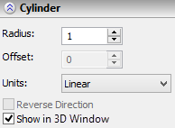
To define an LCS, relative to which the parametric coordinates of the worksurface will be counted, use the option:
|
<L> |
Select target LCS |
The option to cancel a local coordinate system selection is:
|
<D> |
Eliminate target LCS |
The system will automatically define the parametric 2D region of the worksurface being created (on a separate drawing page of the Workplane type). If necessary, you can manually define the boundaries of the parametric 2D region of the worksurface being created, using the nodes on the same or another 2D page. To do that, use the same options as when creating a worksurface based on 2D constructions.
Creating an arbitrary worksurface based on 2D constructions (in the 2D window)
To create a worksurface of this type, you need to call the Construct Worksurface command from the 2D window. Upon entering the command, just like in the previous case, you need to specify the type of the surface being created (the option![]() ,
, ![]() and
and ![]() ).
).
After that, you need to define the parametric 2D region of the worksurface being created. If there are no worksurfaces or planes on the current 2D page, then the system will select the region boundaries automatically according to the page format frame size. If, on the other hand, the current drawing page is already related with worksurfaces or planes, or if you are not satisfied with the system choice, define the boundaries of the parametric 2D region by selecting two 2D nodes with the options:
|
<N> |
Select Node as origin of parametric region |
|
<N> |
Select Node as second border of parametric region |
The start and end points should not coincide. Otherwise, it will be impossible to determine the orientation of the U and V axes.
By default, the range along the Х-axis of the parametric region is mapped onto the range of U parameter, the Y-axis – onto V. This can be changed by the option:
|
<3> |
Shift coordinate axes |
The fixed parameter value of the worksurface being created (the surface radius) is defined in the command's parameters window.
If the worksurface is to be created relative to a local coordinate system, then you need to use the option:
|
<L> |
Select target LCS |
To cancel a local coordinate system selection, use the option:
|
<D> |
Eliminate target LCS |
The visible boundaries of a worksurface on the drawing are by default aligned with the defined boundaries of the parametric 2D region. The visible boundaries can be modified with the options:
|
<B> |
Define Workplane borders |
|
<Tab> |
Switch Workplane borders |
|
<K> |
Eliminate borders |
These options work in the same way as those provided for common workplanes.
Finishing the worksurface creation
You can finalize worksurface creation by clicking ![]() (in the automenu or in the command's parameters window).
(in the automenu or in the command's parameters window).