Parametric Region |
  
|
The parametric 2D region of a worksurface is defined on one of 2D pages of the current document. The size and position of the parametric region in the drawing units is defined either by the system automatically or by the user (by specifying two 2D nodes as the diagonal corners of the region). The size of this region in the parametric coordinates is always constant, depending on the type of the surface being created (entered as the "ranges" in the table above). The region extents along the Х-axis are mapped onto the allowed range of the parameter U, along the Y-axis – onto V (the reverse configuration is also supported).
In the cases when the position and size of the parametric region are defined by the user (by selecting two 2D nodes), the direction of the worksurface axes is determined by the nodes selection order and position. The diagrams below show the configurations of the UV-axes directions with respect to the order of node selection.
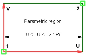
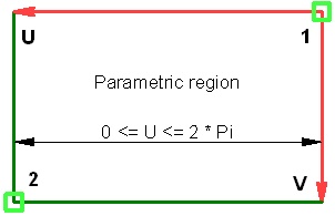
When the parametric 2D region of the worksurface is defined automatically, the axes are always directed as shown on the right-hand-side figure.
In spherical and toroidal coordinate systems, both parameter axes represent angular coordinate values. The exception is the cylindrical coordinate system. Since a cylinder can be "unwrapped" onto a plane without distortions, linear units can be used as cylindrical coordinates. The V-axis units are always linear, while the units of the U-axis can be either angular (the angle between the radius vector and X-axis) or linear (U being the linear distance as measured along the cylinder unfolding).
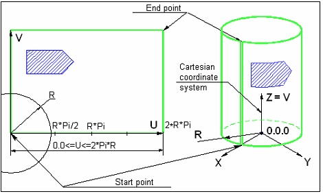
When using linear units along the U-axis of the cylindrical coordinates, the second 2D node defines only the axes orientation. The size of the parametric region along the U-axis in this case is equal to 2pR, where R is the cylinder radius. The diagram below shows the way of defining the parametric region for a cylindrical surface, when linear units are used in both axes.
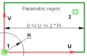
When using angular units along the U-axis in cylindrical coordinates, both nodes are used. The linear distance between the two nodes along the U-axis is considered equal to the angular value of 2p. The linear coordinates in this direction will be converted into the angular ones based on this constant.
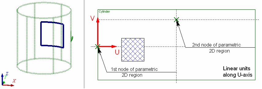
The choice of units along the U-axis – linear or angular – depends on a particular task. If the 2D construction to be carried over on a cylindrical worksurface is described in linear units, then it may be more convenient to use linear units along the both axes of the cylindrical coordinates. In this case, the 2D construction will be carried over to the 3D space preserving all relations between the construction elements. Use of angular units in such a situation will cause distortions in the transition from 2D to 3D. As in illustration, consider a simple example of creating a 3D profile on a cylindrical worksurface using a 2D hatch of square shape. One can easily see that the profile shape is far from square when using the angular units along the U-axis. Meanwhile, when using the linear units, the 3D profile matches the shape of the hatch.
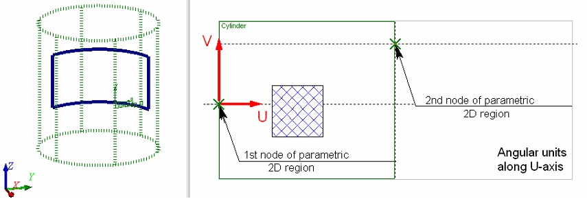
Use of the angular units along the U-axis of the cylindrical coordinate system makes sense only in the cases when the original 2D constructions are described using angular values. For instance, in the following example, the original 2D data for creating a model of a heat exchanger are defined in the angular values on the surface of a cylinder. Use of angular units helps easily getting the desired result (provided that the boundaries of the parametric region of the worksurface were defined correctly).
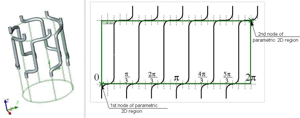
To be comfortable when working with angular units, use the following rule. The distance between the 2D nodes along the U-axis must be set so that the total width of the parametric region along the U-axis (that is, the respective distance between the nodes defining its boundary) is a multiple of 360 (in degrees), or 2p (when using radians).
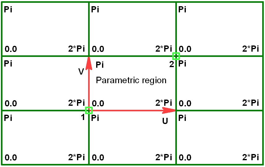
When working with worksurfaces of any type, keep in mind the following. Any of the worksurfaces are periodic in one or both UV-parameters. Therefore, a parametric surface has cycles in the direction in which it is periodic. The diagram below shows periodicity of a parametric 2D region for spherical and toroidal surfaces.
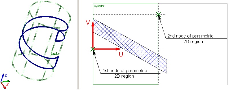
In the case of a cylindrical surface, the parametric 2D region cycles only along the U-axis.
The Fixed Parameter and the Cartesian Coordinate System of the Worksurface
A fixed parameter value (two parameters – in the torus case) is defined with a numerical value. When creating a worksurface by an existing geometrical surface, the fixed parameter value is determined by the specified offset along the radius of the source geometrical surface.
The position of the worksurface in space is defined by selecting a Cartesian coordinate system. The parametric coordinates will be counted with respect to the system. An arbitrary LCS can be selected as such a system. If no local coordinate system is specified, the global coordinates are used.
When constructing a worksurface by an existing geometrical surface, the coordinate system of the source geometrical surface is used as the Cartesian coordinate system.