Offset Surface |
  
|
Calling the command:
Icon |
Ribbon |
|---|---|
|
3D Model > Advanced > Offset Surface Surfaces > Operations > Offset Surface |
Keyboard |
Textual Menu |
<3SO> |
Operation > Offset Surface |
An offset surface enables users to create equidistant surfaces from body faces or surfaces. The offset is performed by the normal to the faces chosen: along or contrary to the normal at a given value. The operation is helpful for creating external surfaces of thin-walled parts basing on the built internal surfaces or vice versa.
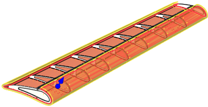
Setting the operation
Upon calling the command, you should select the faces for the offset to be built from. Face selection option is active by default in the command's automenu:
|
<T> |
Select Face |
The option is linked with the Faces list in the command's parameters window. As long as the option and the list are active you can select desired objects in 3D scene or model tree anytime using ![]() . Two selection filters are available in this case:
. Two selection filters are available in this case:
![]() Select Operations
Select Operations
Allows to select an operation that form a surface-body. Offset surface will be created using all faces of such body, offset value will be common for all faces.
![]() Select Faces
Select Faces
Allows to specify faces directly. All faces should belong to one body (solid or surface), you cannot select faces of different bodies or surfaces. The selected faces can be smoothly-joint, having common edges, or not joint.
If you activate the Operation box in the command's parameters window using ![]() , then faces selection becomes unavailable, so you can only select an operation.
, then faces selection becomes unavailable, so you can only select an operation.
![]() Select Operations
Select Operations
Upon selecting an operation, its icon and name are displayed in the Operation box in the command's parameters window. You can ![]() Clear the selection, suing button located to the right. The list of faces located below is not used in this case.
Clear the selection, suing button located to the right. The list of faces located below is not used in this case.
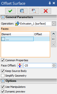
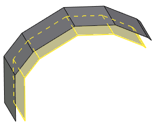
Offset value is specified in the Face Offset input box below for all faces at once. Positive values are applied normally to each of the faces, negative - in opposite direction. Offset manipulators are not displayed.
Selecting another operation replaces the current selection. Selecting a face of the same body results in using this particular face instead of all faces, so the further work with the command is performed as described below for the faces selection case. Selecting a face of a different body is impossible, as long as an operation is selected.
![]() Select Faces
Select Faces
Upon selecting a face, its icon and name appear in the Faces list of the command's parameters window. Selecting another faces adds it into the list. Rows of the list can be selected using ![]() . Multi-selection is performed via
. Multi-selection is performed via ![]() +<Shift> and
+<Shift> and ![]() +<Ctrl>. Face corresponding to the selected row of the list is highlighted in red in 3D window, other selected faces are highlighted yellow. You can
+<Ctrl>. Face corresponding to the selected row of the list is highlighted in red in 3D window, other selected faces are highlighted yellow. You can ![]() Expand,
Expand, ![]() Collapse,
Collapse, ![]() Clear the list or delete the selected row (
Clear the list or delete the selected row (![]() Delete Element from the List) using buttons located to the right.
Delete Element from the List) using buttons located to the right.
The parent operation of the selected faces is indicated in the Operation box. The ![]() Clear button of the Operation box also clears the list of faces.
Clear button of the Operation box also clears the list of faces.
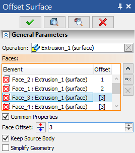
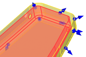
An offset value is displayed in the list for each face. It can be edited using the Face Offset input box in the parameters window or using manipulators in 3D window. Positive values are applied normally to each of the faces, negative - in opposite direction. Direction may also be changed to opposite using the ![]() button located to the right of the offset value input box.
button located to the right of the offset value input box.
The Common Properties checkbox is located below the list of faces. It is enabled by default, so the offset value and offset direction are common for all faces. If you disable the checkbox for some of the selected faces, then offsets of such faces will be defined individually and their manipulators will move separately from others. Common offset value is displayed in the list of faces in square brackets, individual - without brackets.
Finishing input
To finish the command with creating the surface according to the parameters set, do the following:
|
<Сtrl+Enter> |
Finish input |
To exit the command without creating the surface, do the following:
|
<X> |
Exit command |
Additional operation parameters
Keep Source Body. This option enables you to leave the initial body or surface at the 3D scene along with the result. This can be helpful when it is necessary to have both initial and resulting faces at the same time.
Simplify Geometry. For some operations General Parameters or Additional Parameters tabs of the Parameters window have the Simplify Geometry checkbox. Enabling this checkbox will allow the automatic simplification of the resulting geometry. Spline-based surfaces will be replaced by analytic surfaces (segments of cylinder, sphere or torus) where possible.
Options
Dynamic preview. The option is standard for all the 3D Design commands. It enables a simplified representation of the surface being built which dynamically changes when the initial parameters change. The option is enabled by default.
Use Manipulators. The option is standard for all the 3D Design commands and is enabled by default. It enables auxiliary graphical objects – manipulators. There is one type of manipulators in this operation: face offset manipulators.