Creating Macros with Screen Forms |
  
|
Sometimes it is necessary to provide the user with the ability to set some parameters during the execution of a macro using a specially created graphical dialog. For these purposes, the Macro Editor has the ability to create screen forms with controls. Below we will consider the tools of the Macro Editor, which allow you to create macros with screen forms.
Form creation
To create a form in the current Project, use the command:
Macro Editor |
||
|---|---|---|
Icon |
Keyboard |
Textual Menu |
|
|
Project > Add Form |
The command can also be called from the Project window. To do this, place the cursor on the heading of the Forms section in the tree of the current Project and press ![]() . The Add command will be available in the opened context menu.
. The Add command will be available in the opened context menu.
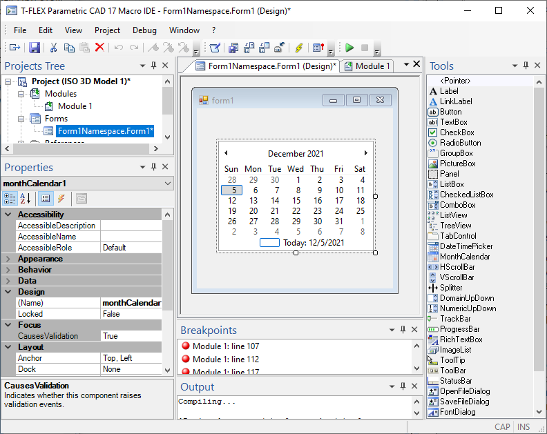
After adding a new form to the Project, a new form window will automatically open in the working window of the macro editor. It contains an empty form layout, ready to be filled with controls. The title of the window contains the name of the form with a qualification in brackets - “(Design)”.
In addition, when the form window is opened, the Properties and Tools service windows are automatically opened.
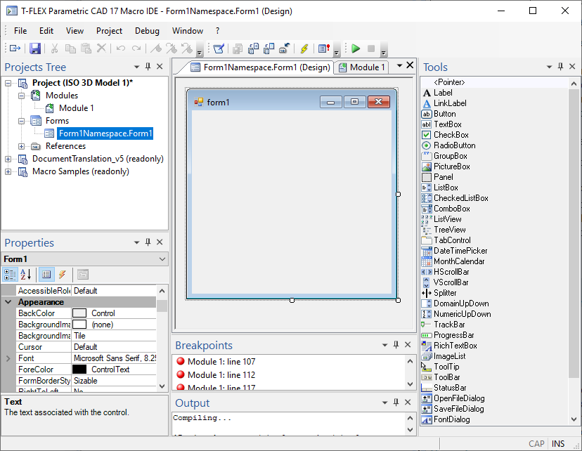
When you add a form to the Project, two new links are automatically added to the list of links: “Systems.Windows.Form” and “Systems.Drawing”.
Tools window
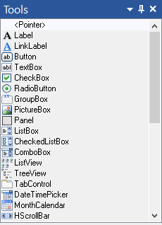
The Tools window opens automatically when you create a new shape. You can independently call the Tools window from the textual menu of the macro editor: View > Tools.
The Tools window contains a set of controls that can be placed on a form. Elements in this window appear only when the form is active. Otherwise, the window is empty.
Properties windows
The window can be called from the textual menu of the macro editor: View > Properties It is intended for viewing and setting properties and events (methods) for the form and elements located in the form. This window remains empty until a form or an element on the form is selected.
Control properties are parameters that define the characteristics of an object (name, color, position, etc.).
Control events are actions performed on a control object, such as clicking a button control. During the execution of the program (macro), the event of the control is associated with the execution of certain commands. For example, the event of clicking on the Button control can be associated with the creation of an object in T-FLEX CAD.
In the upper part of the Properties window there is a list with form elements. To view and change the properties of a form element, select it in the list or use ![]() to select an element on the screen form itself.
to select an element on the screen form itself.
The Properties window works in two modes:
•If the Properties ![]() option is active on the window toolbar, the properties of the element will be displayed in the window.
option is active on the window toolbar, the properties of the element will be displayed in the window.
•If the Events ![]() option is active, then the events are displayed in the window.
option is active, then the events are displayed in the window.
The Properties window is divided into two parts. The left column displays the object property names. The right column displays the property values.
If the window is in the event display mode, the right column of the window displays events that are possible for this type of element. In the left column, the names of the functions that are currently being used for this item and event.
Using the ![]() and
and ![]() buttons, you can sort the list of object properties either alphabetically or by type, respectively.
buttons, you can sort the list of object properties either alphabetically or by type, respectively.
|
1. Property names 2. Property values 3. Event names 4. Event procedure names 5. Property description 6. Event description 7. Element list |
For some properties, strictly defined values can be set. In this case, the field for entering a value will be a combo box, when expanded, the property values that are allowed for selection are displayed.

Placement of controls on the form. Setting item parameters
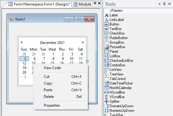
To place controls on a form, you need to do the following:
•Select the form to which you want to add the control.
•Select the required element in the Tools window.
Then you can proceed in two ways. The first way is to press ![]() anywhere on the form. This adds the selected standard size control to the form. You can then drag the control to the desired location on the form and resize it.
anywhere on the form. This adds the selected standard size control to the form. You can then drag the control to the desired location on the form and resize it.
The second way is to specify by two clicks ![]() the position of the opposite diagonal corners of the control rectangle. This immediately sets the position and size of the control.
the position of the opposite diagonal corners of the control rectangle. This immediately sets the position and size of the control.
You can set the parameters for the controls applied to the form using the Properties window. You can select the editable element directly in this window (in the drop-down list above) or in the form using ![]() . After selecting an element, its parameters will be reflected in the Properties window.
. After selecting an element, its parameters will be reflected in the Properties window.
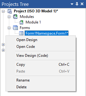
If necessary, you can view the automatically generated code for creating a graphic image of the form. This can be done using the Open Code (Design) command in the context menu for this form in the Project window. The form design code window also opens in the working window of the macro editor. The title of the window includes the name of the form with a qualification in brackets - “(Design)”.
The name of the form design code window is the same as the name of the form window. They differ in icons: ![]() - at the form window,
- at the form window, ![]() - at the form design code window.
- at the form design code window.
After placing all the necessary form elements, you can proceed to setting the form code.
Writing Procedures for Controls in Forms
After you place the controls on your forms, you need to associate those controls with code.
The form code is created in a separate window, similar to the module code window. The title of the window contains the name of the form with a qualification in brackets - “(Code)”.
This window can be invoked in three ways:
• In the Projects window, from the context menu for the selected form, call the Open Code command. This will open a window with the form's code, where you can add event procedures for controls in this form.
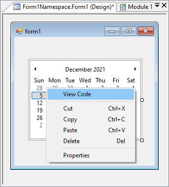
•By calling the Open Code command from the context menu for any form control.
•By ![]()
![]() on a control on a form. In this case, a procedure for processing the control method for the corresponding element will be automatically created in the window that opens. Events for each control are set by default.
on a control on a form. In this case, a procedure for processing the control method for the corresponding element will be automatically created in the window that opens. Events for each control are set by default.
You can switch between the form window and the code window either using the context menu commands for this form (Open Design, Open Code), or using the corresponding tabs located at the top of the working window of the macro editor.
Like the module code windows, the form code window is a text editor. By default, the form code window contains only the form initialization routine.
The form code usually consists of a form initialization procedure (it is created automatically when the form code window is first opened) and event handling procedures for form controls.
To create an event handling procedure for a form object, select the required element, switch the Properties window to the Events mode, select the required event in the list and press ![]()
![]() . An empty procedure for handling the selected event for this form element is automatically added to the code window. The body of the procedure is empty, it is filled in by the user.
. An empty procedure for handling the selected event for this form element is automatically added to the code window. The body of the procedure is empty, it is filled in by the user.
For some controls, you can also use simply double-clicking ![]()
![]() on an item in the form. This adds a procedure for handling the main event of this control to the form code.
on an item in the form. This adds a procedure for handling the main event of this control to the form code.
An example of macro with display form
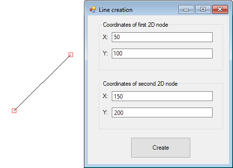
Consider an example of a macro written in the Visual Basic programming language. When executing a macro, a line is created between two 2D nodes. The coordinates of these nodes are set in the dialog.
Initially, in the “CreateLine.grb” project, the “LineForm” form was created and controls are placed on it, in which the coordinates of 2D nodes will be set. A control element has been added to the form - a button, when clicked, a function will be launched that creates 2D nodes and a line between them.
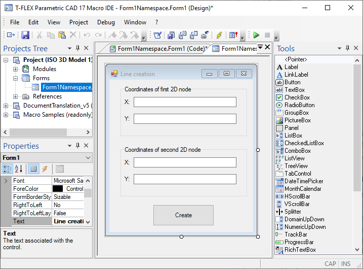
After placing the controls on the form, you need to create a handling of the event of clicking on the control - the button. To do this, select this element in the form, go to the Properties window and set the event mode ![]() in this window. In the right column of the “Click” event, click
in this window. In the right column of the “Click” event, click ![]() , this will create the “button1_Click” procedure. The same effect could be achieved by pressing
, this will create the “button1_Click” procedure. The same effect could be achieved by pressing ![]()
![]() on the button control.
on the button control.
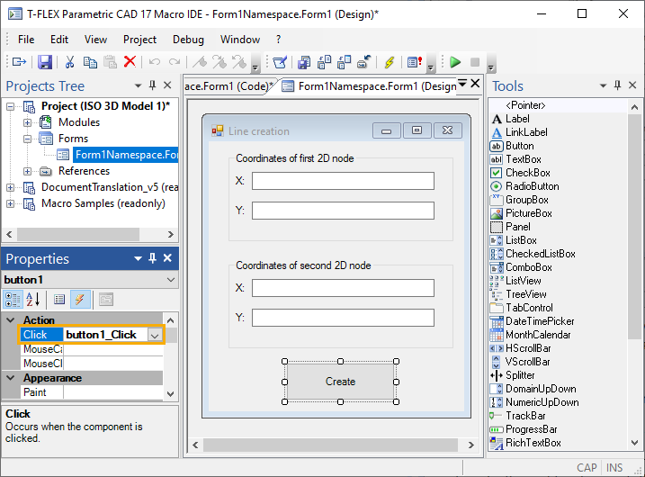
In the form code window that opens, you need to write the “button1_Click” procedure.
The figure below shows the form code window with the “button1_Click” function, in which the variables “X1”, “Y1”, “X2” and “Y2” are assigned values from the controls - editors textBox1, textBox2, textBox3 and textBox4, and the function is called (macro) "CreateLine".
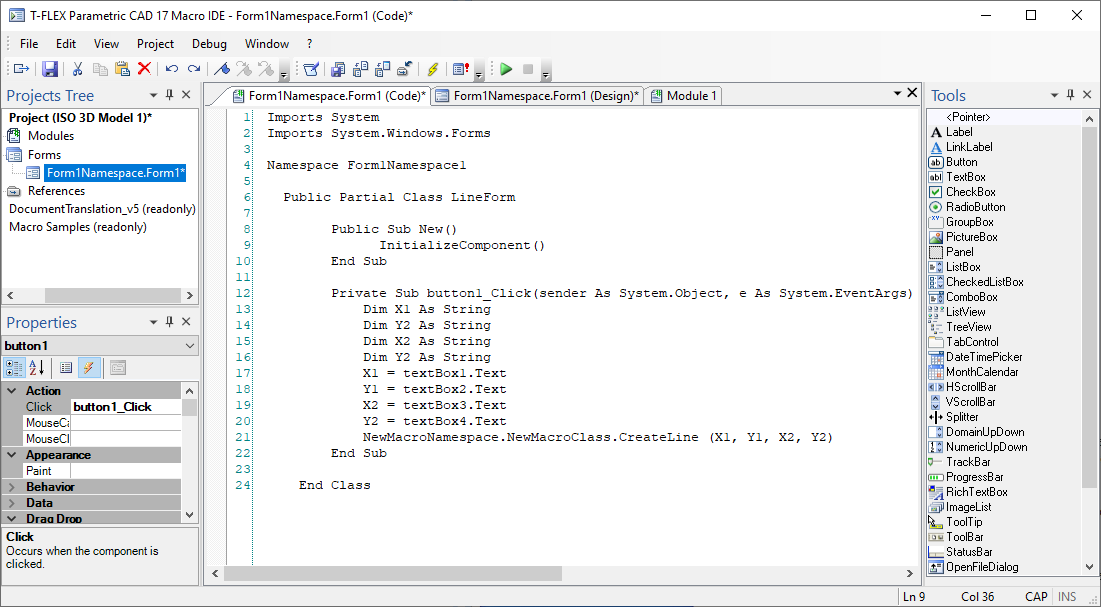
After that, create a module in the Project. The module code will consist of two functions. The “ShowDialog” function (a standard development environment function) will display the screen form after running the macro. The “CreateLine” function, which has been defined, creates 2D nodes whose coordinates are the values specified by the user through the “LineForm” form dialog, and the line between these nodes. The code for this module is shown below.
'Declaring references
Imports System
Imports TFlex
Imports TFlex.Model
Imports TFlex.Model.Model2D
'Declaring namespace
Namespace NewMacroNamespace
'Declaring class
Public Class NewMacroClass
'The function, which will display the screen form «form» when executed
Public Shared Sub ShowDialog()
Dim form As LineForm
form = new LineForm()
form.ShowDialog()
End Sub
'The function with parameters (the macro), which creates a graphic line between two 2D nodes.
'Coordinates of those nodes are input in the function as the dialog parameters
Public Shared Sub CreateLine(ByVal NodeX1 As String, ByVal NodeY1 As String,
ByVal NodeX2 As String, ByVal NodeY2 As String)
Dim document As Document
document = TFlex.Application.ActiveDocument
'Opening block of documents changes
document.BeginChanges("Creating graphic lines")
'Creating graphic line and 2D free node objects
Dim line As ConstructionOutline
Dim node1 As FreeNode
Dim node2 As FreeNode
Dim X_1, Y_1, X_2, Y_2 As Double
X_1 = System.Convert.ToDouble(NodeX1)
Y_1 = System.Convert.ToDouble(NodeY1)
X_2 = System.Convert.ToDouble(NodeX2)
Y_2 = System.Convert.ToDouble(NodeY2)
'Creating 2D free nodes
node1 = new FreeNode(document,new Parameter(X_1),new Parameter(Y_1 ))
node2 = new FreeNode(document,new Parameter(X_2),new Parameter(Y_2 ))
'Creating graphic line between two nodes
line = new ConstructionOutline(document,node1,node2)
'Closing block of document changes
document.EndChanges()
End Sub
End Class
End Namespace
After running the macro in T-FLEX CAD, the “LineForm” dialog will be called. When you click on the control - the OK button, a segment between two nodes will be drawn in the drawing field.
