Sheet Metal |
  
|
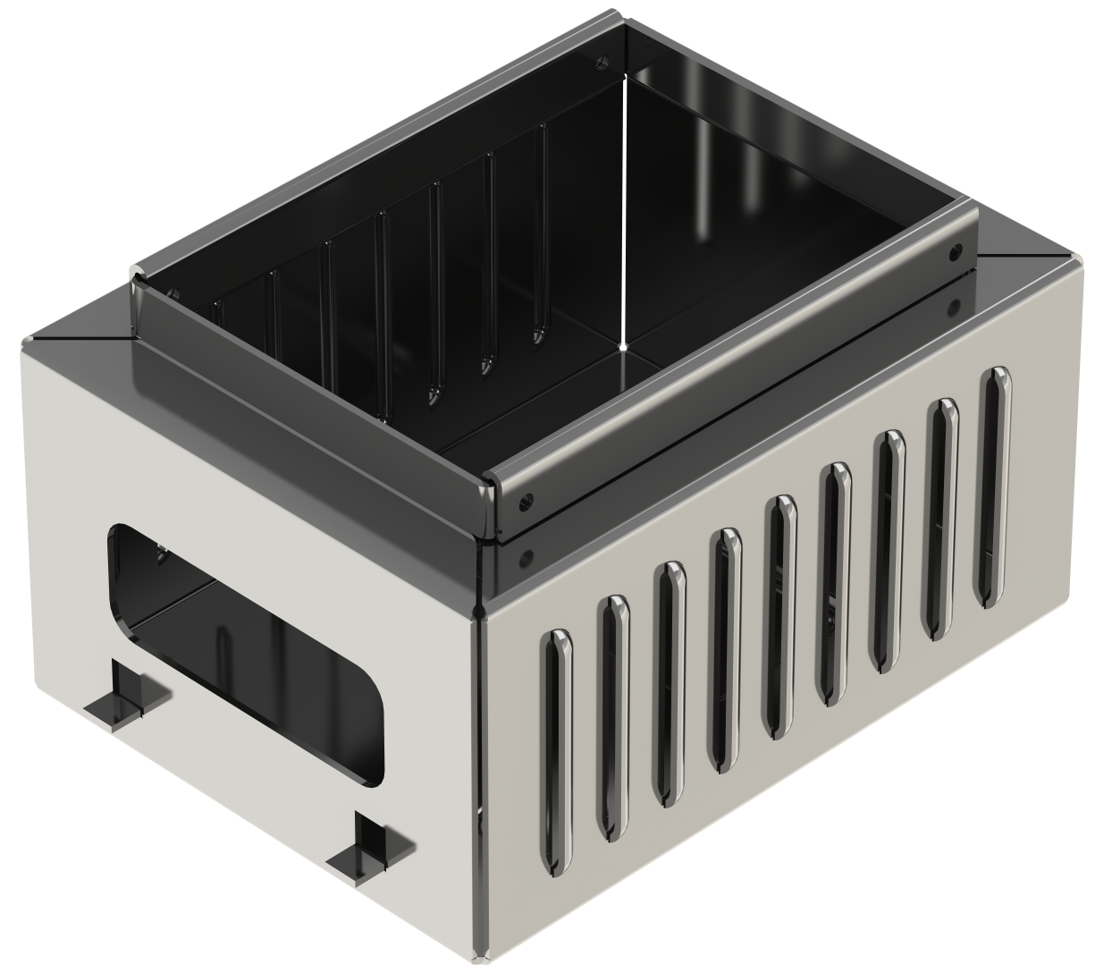
Sheet metal commands and operations facilitate solving problems of modeling details manufactured by the sheet metal stamping method. They allow to create an initial flat part (workpiece) of the specified thickness and then perform various shape manipulations, such as bending about a selected line, attaching flanges to the workpiece, creating punches and hems. Once modeling is finalized, the part can be unbent to the unfolded sheet workpiece, you can create its drawing, bend table and then re-bent to the actual part shape.

Sheet Metal Example
The special forming feature command in the sheet metal group of commands helps to create various commonly used forming features, such as beads, ribs, flanges, airways, cradle.
When working with sheet metal, you can use not only the specialized commands described in this chapter but also general-purpose commands (Extrusion, Primitive, Boolean operations, Hole and so on).
In some cases applying general-purpose commands may cause issues with unfolding.
In addition, it is possible to create flat patterns and sheet parts based on solids using the Convert Body to Sheet Metal operation and to create sheet parts over two sections with the Lofted Bend operation.
Note that the sheet metal operations do not account for possible material deformations. Rather, those are based purely on geometrical calculations.
Topics in this section:
•General Information on Working with Sheet Metal