Transform Faces |
  
|
Calling the command:
Icon |
Ribbon |
|
3D Model > Special > Surfaces > Transform Faces Surfaces > Operations > Transform Faces |
Keyboard |
Textual Menu |
<3ZT> |
Operation > Surfaces > Transform Faces |
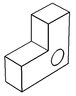
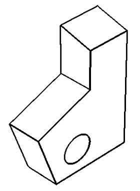
This command applies a transformation to one or several selected faces. The command is mostly used for handling imported models, however it can be helpful in other cases as well.


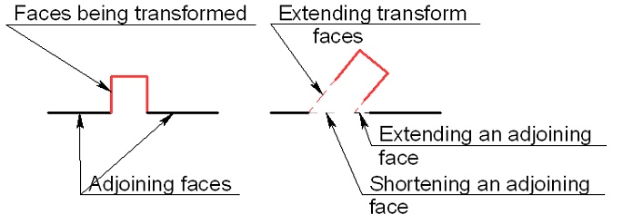
By executing the command, the selected faces are moved to a new position and, if requested, extended (or trimmed) to achieve an intersection with the surfaces of the adjoining faces. The adjoining faces, in turn, are extended (or trimmed) to the intersection with the faces being transformed.

The correctness of the command behavior can be guaranteed only if the topology of the resulting model is unchanged. If the model topology changes, the result of the operation may be incorrect.
When selecting the faces to transform, the same mechanism is used as in the command Delete Faces: the faces to transform can be specified directly or implicitly. Defining transformation parameters of the selected elements is done similar to that in the command Transform Element.
To use the command, do the following sequence of steps:
1. Specify faces to transform.
2. Define transformation parameters.
3. Confirm operation creation.
Specifying faces to transform
To specify the faces to transform, use the option...:
|
<F> |
Select Elements |
...or corresponding filters in the filter toolbar.
When using this option, you can select not only faces, but also edges with loops. The selected elements are put in the Faces list.
To cancel selection of all elements, use the option:
|
<X> |
Cancel selection of all faces and surfaces |
If edges or loops are selected, the Face Selection Pattern parameter becomes available. The effect of this option is described in the command Delete Faces.
When selecting a set of edges, the default option is:
|
<G> |
Smooth edge chain selection mode |
To select individual edges, turn off this option.
Specifying a Transformation
Special manipulator appears in the scene after selection of the first element. It helps you to change the position of the selected faces. Procedure of specifying transformations is described in detail in the Transform Element command description. The exact values of translations and rotations can be set in the parameters window.
Use the following options to select the coordinate system relative to which the transformation will be performed:
|
<1> |
Source CS on source operation |
|
<2> |
Select LCS for current transformation |
Option ![]() is active by default. The manipulator is in the center of original operation bounding box. The drop-down list of the option has the second variant of coordinate system positioning - option
is active by default. The manipulator is in the center of original operation bounding box. The drop-down list of the option has the second variant of coordinate system positioning - option ![]() . When you select this option, the manipulator will be in the center of the bounding box that bounds all movable face.
. When you select this option, the manipulator will be in the center of the bounding box that bounds all movable face.

Source LCS on source operation LCS for current transformation
Option ![]() allows you to select any LCS for specifying the transformations.
allows you to select any LCS for specifying the transformations.
The operation can be confirmed either at the stage of selecting the elements to transform or at the stage of defining the transformation parameters.
Topics in this section: