Transformations of 3D Fragment |
  
|
Controlling additional transformations is carried out with the help of a manipulator in the 3D window and group Transformations of the parameters window and the Group of Transformations dialog of the Main transformations section of the parameters window. The manipulator is always present upon insertion of a 3D fragment, if the option Use Variable Manipulators is turned on in the parameters window.
The manipulator enables to define an unlimited number of translational transformations along the indicated axes in-plane shifts or rotations of selected axes by a required angle in the required plane. The manipulator represents itself an image of the coordinate system. The coordinate axes are connected to each other by color arcs; adjacent planes are connected with each other via conditional small color squares, the manipulator center is marked by a grey ball. Different parts of the manipulator are the active elements intended for defining certain transformations:
•the manipulator axes are intended for defining translations;
•the manipulator arcs are used for defining rotations;
•the manipulator center is used to manually enter the mode of dynamic snapping.
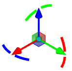
See the detailed description of manipulators in the LCS Manipulators for Transformations of 3D Elements section.
For defining transformation with the help of the manipulator a user has to choose an active element of the manipulator by pressing ![]() . Then, without releasing the mouse button a user can move the cursor. The transformation will have been set upon releasing the mouse button.
. Then, without releasing the mouse button a user can move the cursor. The transformation will have been set upon releasing the mouse button.
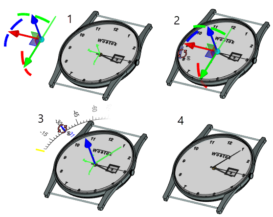
1. Begin with inserting a fragment (the minutes arm) by selecting the edge on the arm pin to define the target LCS (of the arm fragment position)
2. Turn the arm. To do this, select the desired element of the manipulator and depress the left mouse button
3. Drag the mouse whilst holding the mouse button down. Turn the fragment about the axis
4. Complete the transformation definition by releasing the mouse button
Also, after manipulators selection it is possible to release the mouse button, shift the cursor and choose a new element (indicate a new point in space) for fixing transformation by pressing ![]() twice.
twice.
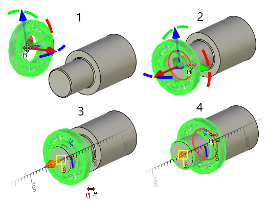
1. Start inserting the fragment (the bearing)
2. Select the round edge to define the target coordinate system (the fragment's position)
3. Click to select the manipulators axis to define the translation along the axis
4. Select the round edge to define the final point of the translation
Click at manipulator center signifies transition to operations for modifying the target coordinate system. Simultaneously, the mode of dynamic snapping gets activated. In this mode, the fragment image is attached to the cursor. Upon bringing the cursor to the elements of the model, the fragment image will be immediately put in a position showing the location of the fragment in case the element is selected. In this mode it is possible to click at the free spot in space or choose an element of the model for attaching. In the first case, new additional transformations for placing the fragment at the spot of a click are created. After choosing the new element of the model for attaching, all previously defined transformations may be deleted.
Group Transformations in the parameters window can be used for controlling, correcting numerical values, creating or deleting transformations of a 3D fragment. In the special field the list of all additional transformations, defined at the moment for a 3D fragment, is shown. Each transformation is marked by a special symbol, denoting its type (translation or rotation about some axis). If the value of the transformation is set via a constant, then this value is shown next to the symbol. If the transformation was attached to the element of the model, then the name of the element is indicated next to the symbol. The elements of the list are shown in the order in which there were created. Several successive transformations of similar type are automatically summed up.
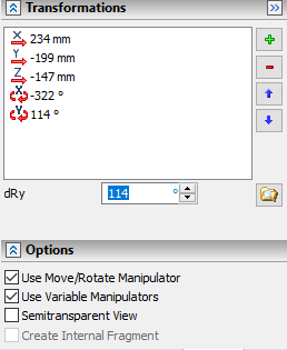
The user has also a capability of creating individual transformations groups for 3D fragments. Classifying transformations into groups allows the user to create simultaneously several variants for the 3D fragment locations in the assembly.
For example, let us suppose there is a variant of the room’s 3D layout. It is required that the fragment (barrel) change its location depending on the location of walls and addition of new objects to the layout.
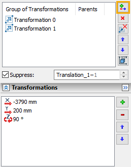
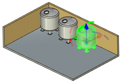
To do so, in the parameters window of the 3D fragment (barrel) in the Main Transformations section we find the Groups of Transformations dialog. With the help of the ![]() button we add the transformations group, namely we specify the values for translations along the X and Y axes and rotation around the Z-axis.
button we add the transformations group, namely we specify the values for translations along the X and Y axes and rotation around the Z-axis.
It is important to remember that by default all transformations for a 3D fragment are created in a single transformations group.
Each transformations group has it name. The elements of the list are shown in the order that correspond to their creation.
To control visibility of various locations of the fragment there is the Suppress flag. Next to the flag there is a field where the numbers can be entered or the numeric variables can be written down. If the value different from zero is entered into the field, the transformations group becomes suppressed. To make the work in the assembly more convenient let us specify the visibility of the fragment’s locations with the help of the variable.
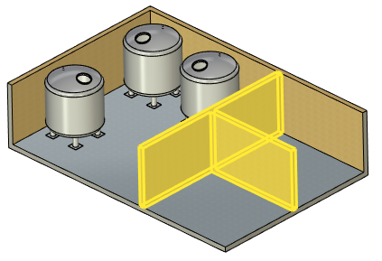
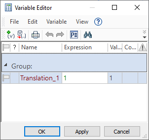
After specifying several positions of the fragment (barrel) with the help of the transformations group we obtained the capability of manipulation of its translation in the easiest and fastest way.
In this case for displaying the changes in the transformations in the 3D window it is required to use the 3D model update button ![]() .
.
Upon attaching a fragment to the connector, the system can automatically move to defining additional transformation, if the corresponding instructions are set in the connector (see Local Coordinate Systems section).
After insertion 3D fragment all prescribed additional transformations are recorded in the common transformations list of the 3D fragment. A separate record is generated for each additional transformation in the transformations list of the 3D fragment.
For more information about transformation 3D elements, see Transformations of 3D Elements section.