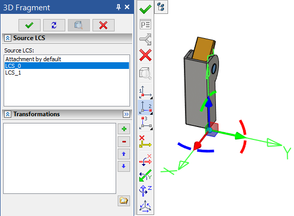
3D Fragment Attachment |
  
|
Selection/creation of the source coordinate system
The automatic sequence of the system steps for attaching a 3D fragment depends on whether predefined local coordinate systems existed in the 3D fragment model, and, if so, how many:
•If there is exactly one LCS in the 3D fragment model, and its parameters state that it can be used for attaching the 3D fragment, it will be automatically selected by the system as the source coordinates. The system will then proceed to the next step - defining the target coordinate system. If there are more than one LCS in the 3D fragment document, but only one of them is specifically designated as the source coordinates, the system behavior will be the same. (Refer to the topic Preparing document for use as 3D fragment for details.)
•If a 3D fragment model contains several LCS all suitable for fixing the 3D fragment, then T-FLEX CAD picks up the default fixing (by the global coordinate system) and proceeds to defining the target coordinate system. To select a coordinate system, you need to switch to the special mode of selecting/creating the source coordinate system.
•If no local coordinate systems exist in the 3D fragment model, then T-FLEX CAD picks the default fixing (by the global coordinate system) and proceeds to defining the target coordinate system. To create a new source coordinate system, you need to switch to the special mode of selecting/creating the source coordinate system.
Mode of selecting/creating source coordinate system
Those type is operated in a separate 3D window, in which the 3D fragment model is loaded. This 3D window is launched forced from the 3D fragment creation command by the option:
|
<S> |
Select or Create Source LCS |
After opening the new window, in addition to standard options, the following options can be initially found in the automenu:
|
<1> |
Select 3D node or vertex as LCS origin |
|
<2> |
Select point to Define Direction of X-axis |
|
<3> |
Select point to Define Direction of Y-axis |
|
<C> |
Reset target LCS |
|
<A> |
Rotate LCS around X-axis by 90° |
|
<O> |
Rotate LCS around Y-axis by 90° |
|
<Z> |
Rotate LCS around Z-axis by 90° |
|
<9> |
Change LCS axes orientation |
The option ![]() remains active, indicating that the system is in a special mode of operation with the source coordinate system. Selecting the option
remains active, indicating that the system is in a special mode of operation with the source coordinate system. Selecting the option ![]() returns the user to the assembly and enables the task mode of the target LCS. This option is intended for switching to actions for setting the geometric parameters of an adaptive fragment (for a detailed description, see Adaptive 3D fragments).
returns the user to the assembly and enables the task mode of the target LCS. This option is intended for switching to actions for setting the geometric parameters of an adaptive fragment (for a detailed description, see Adaptive 3D fragments).
When the option ![]() is running, the selection of an existing LSC is carried out in a 3D window or from a list in the parameters window.
is running, the selection of an existing LSC is carried out in a 3D window or from a list in the parameters window.

The system allows creating a new LCS based on the 3D fragment's geometry. To activate the mode of creating new source LCS, the first element for determining the origin of the coordinate system has to be selected in a 3D model. At the same time, it is possible to select any appropriate elements of the model in accordance with the active filters of the selector on the system toolbar. After choosing the origin of the new source LCS, the remaining options for defining LCS will appear in the automenu. Creation of the coordinate system is carried out by the same principles as in the specialized command for creating LCS. Similar options and tools are used in both cases. The center and direction of the LCS axes are prescribed. In addition, the options for cyclical rotation and rotation of axes by 90 degrees are available. In this chapter we will omit detailed description of the LCS creation process.
When creating a new LCS, keep in mind that it is not created in the 3D fragment file. Rather, it belongs to the current 3D fragment operation and is stored in the assembly document. The created source coordinate system cannot be displayed in the assembly. To modify it, you need to call the 3D fragment editing command and enter the mode of selecting/creating the source LCS.
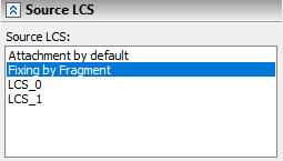
When the new source LCS is being created, the new line Fixing by Fragment will appear in the Source LCS list for the fragment.

To exit the mode of selecting/creating the source LCS, use the button ![]() .
.
Selection/creation of the target coordinate system
The mode of selecting or creating the target coordinate system is turned on by the automenu option:
|
<T> |
Select or create target LCS |
In most cases this option is activated automatically after choosing the fragment file and after exiting the mode of creating the source LCS. If a suitable LCS is found in the assembly model then the user actions amount to selecting the LCS in the assembly, to which the fragment source coordinate system should be snapped. If no LCS is selected in the assembly, then the global coordinate system of the assembly will be used as the target coordinate system.
One can also create a new target coordinate system based on 3D model elements. The target coordinate system is constructed using the same tools as those for constructing the source one. The main difference is in that the all actions are performed in the main 3D window for the current assembly. The 3D fragment model is positioned in the space according to the parameters of the target coordinate system being defined.
The options for defining elements of the new target coordinate system appear after selecting the origin point of the LCS. Upon selecting the origin, you can proceed with orienting X and Y axes.
In case you couldn't orient the LCS as desired from the beginning, you can use the tools for coordinate system redefinition. Those allow quickly rotating an existing LCS around its axes by 90 degrees (![]() ,
,![]() ,
,![]() ), cyclically reassign the axes of the coordinate system with the fixed origin (pressing
), cyclically reassign the axes of the coordinate system with the fixed origin (pressing ![]() switches the axes assignment).
switches the axes assignment).
|
|
|
Fragment position in absolute coordinates |
Fragment position after selecting an edge for target LCS |
Fragment position after using the tool of rotating X-axis by 90°. |
To reset all data currently used for defining the target coordinate system, use the automenu option:
|
<C> |
Reset target LCS |
Choosing 3D connectors
3D connector can be chosen in the mode of selecting or creating target coordinate system activated automatically right after entering the fragment insertion command (option ![]() ). In this mode it is necessary to make sure that the selector's filter for choosing connectors
). In this mode it is necessary to make sure that the selector's filter for choosing connectors ![]() is activated on the system toolbar.
is activated on the system toolbar.
For searching connector on some part, bring the cursor to one of the elements associated with the connector. In standard elements, for example, in bolts, the screw-threaded faces of the bolt shaft can be chosen as an associated element. Already upon bringing the cursor to such element, the connector is highlighted. Press ![]() for choosing connector.
for choosing connector.