Preparing Document for Usage as 3D Fragment |
  
|
Any T-FLEX CAD document can be customized to simplify in certain circumstances its usage in assemblies as a 3D fragment.
Customizing document status
3D fragment tab in Set Model Parameters command provides possibility to specify default LCS used for fragment fixing, specify type of insertion, set parameters for automatic Boolean operation.
In the Set Document Parameters command dialog on the 3D Fragment tab, you can specify the name and save folder of the fragment file when it is inserted into the assembly, the method of insertion and the general fixing LCS, the layer in the assembly on which this fragment will be automatically placed; set the default source coordinate system, configure parameters for automatic Boolean operation.
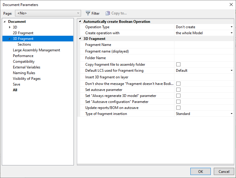
Automatically create Boolean Operation
When inserting a 3D fragment, one can automatically create a Boolean operation of a specified type. The target body will be the selected body in the assembly, while the tool body - one of the bodies of the 3D fragment, or all fragment bodies at once.
Setting up automatic creation of Boolean operation is performed with the help of several parameters:
Operation Type. This parameter defines the type of the Boolean operation (addition, subtraction, intersection) that will be created upon inserting the fragment in the assembly. The type can be selected from the list.
Create operation with:
•Use the whole Model. With this option checked, the whole 3D model of the fragment will be used as the target body of the Boolean operation.
•Use single operation. Selecting this option makes the Boolean use just a single operation within the fragment. The desired operation can be selected from the list of all existing operations.
In the case when a body is used in the Boolean, that is not visible when working with the document of the 3D fragment, it is possible to place it in a special layer marked as Visible only when model is used as a Fragment.
Let's take an example of the use of automatic creation of a Boolean operation when inserting a fragment. Suppose there is a 3D model of the wall of the house in which you need to insert a window as a 3D fragment.
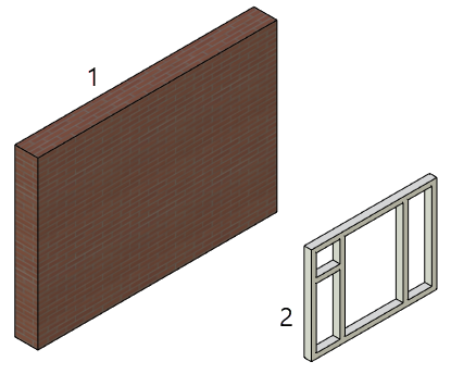
1. House wall model
2. Window model in a separate fragment
To do this, the window model must be created in a certain way. You need to specially create a parallelepiped body on top of the window, along which an opening in the wall will be cut to insert the window.
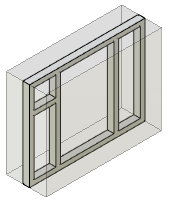
Then you need to open the document parameters, the 3D Fragment tab (see above). Set the Operation Type - Subtraction, Create operation with - operation of creating a parallelepiped body (for example, Extrusion_2).
Then you need to go to the fragment with the model of the wall of the house, call the fragment insertion command, insert the window fragment into the desired location and click ![]() .
.
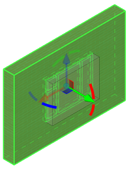
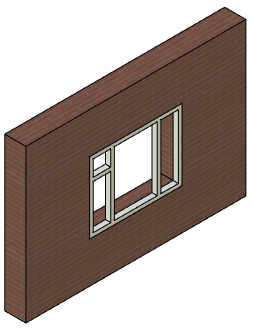
As a result, the inserted window fragment will be subtracted from the model of the house wall.
3D Fragment
Fragment Name. The parameter specifies the name with which the fragment will be displayed in the assembly model tree in the format Name_1 (ISO 3D Model 1.grb).
Fragment name (displayed). The parameter specifies the name with which the fragment will be displayed in the assembly model tree in the format Name_1. The fragment name can be set to a variable, for example - {a}. When inserting such a fragment into an assembly, its name may be different depending on the value of the variable.
Folder Name. This parameter specifies the name of the folder into which the fragment will be placed in the assembly’s model tree.
Fragment’s name and folder’s name are read from the fragment’s file only upon creation of the new fragment. If the values of these parameters are changed, then upon update of the fragment in the assembly the name and the folder will remain the same.
Insertion method. From the drop-down list one of the options can be selected:
•Standard. Upon insertion into the assembly the translation of the fragment is possible only with the help of the manipulator of LCS (dynamic translation is disabled);
•Fastener. When inserted into the assembly the fragment dynamically moves after the cursor of the mouse;
•3D arrangement. This method of insertion is used for quick creation of the arrangement in 3D scene. In the fragment’s file special attachments to the floor, walls, ceiling, horizontal surfaces must be created. These attachments are defined by means of connectors with the specific parameters;
•By points. A fragment can be fixed to the selected in the 3D scene points upon insertion. Its size changes according to the distance between the points.
•Smart fragment (macro). This method of insertion is used for parametric fragments whose insertion scenario is described in the program (macro) stored directly in the file of the given fragment or in the external module (DLL). When inserting the file as a fragment the user-specified macro will be executed.
Default LCS used for Fragment fixing is selected from the list. The list contains all local coordinate systems of the model that have the flag Use for Fragment insertion set. When inserting such document as a 3D fragment, the thus defined coordinate system will be automatically offered as the source LCS.
If necessary, the permitted degrees of freedom can be set in the parameters of the prepared coordinate system, which will insure the correct behavior of the given 3D fragment in an assembly in the mode of moving mated elements (see the Mates and Degrees of Freedom chapter).
For uncomplicated parts, which can be conveniently inserted into the assembly in the mode of dynamic snapping, the given mode can be turned by default.
Insert 3D fragment on layer. This parameter defines the name of the layer onto which the fragment will be placed upon its insertion into the assembly. If in the fragment’s document the “Insert on layer” parameter is enabled, but upon insertion of the fragment into the assembly this layer does not yet exist, then this layer is created automatically upon request.
Don’t show the message “Fragment doesn’t have bodies”. By default this parameter is disabled. In this case the system does not allow for insertion, into the 3D assembly, of the fragment in which the 3D model is absent or suppressed. The corresponding message in the diagnostics window appears as comments. When this flag is enabled the system allows for insertion of “empty” fragment without issuing any messages.
You can define options for section views on 2D projections on the Sections tab.
For some models (future components of assemblies) it can be helpful to define special settings for preventing their cutting when used in section views of 2D projections. For example it is known that bolts should not be cut on section views of assembly drawings. This option will help to avoid time consuming manual customization of 2D projection parameters for assemblies that contain such parts.
New condition can be created with the help of + button. Section Application Condition section will appear with the lists of conditions and LCS names.
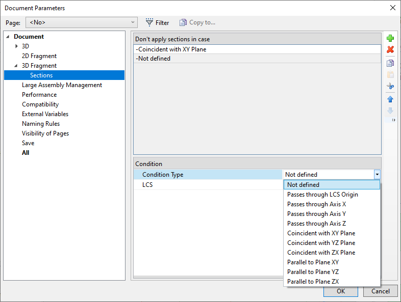
Conditions are organized in relation to the alleged source fragment LCS that exists in a document of a future 3D fragment. For example a part may remain uncut if a section plane goes through a specified axis of the source LCS, or coincides with one of the main LCS planes.
Assembly variable definition
You can assign an assembly variable counterpart for any external variable of the current document. This can be done in the case, when the external variable drives, for instance, a characteristic parameter (such as, say, diameter), while the assembly variable name has already been defined (for example, D). When assembling this document as a fragment, this assembly variable name will be automatically substituted for the fragment variable in the dialog for defining external variable values (provided that this variable exists in the assembly).
The assembly variable name can be defined in the variable editor. Detailed information on working with the variable editor is available in the Variables chapter.
Using fragment dimensions in assemblies
3D dimensions placed inside the fragment document can be "raised" into the assembly. To do this, in the parameters window of the size creation/editing command, on the Common tab, you need to enable the Show on 3D fragments checkbox.
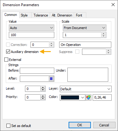
Dimensions raised in 3D into an assembly of fragments can be used for two purposes:
•As decorative - they show the nominal size;
•As control dimensions - such dimensions are used to set the values of the external variables of the fragment by editing their nominal value. To do this, you need to set the nominal value type Manually in the dimension parameters, and write the name of the external variable in the expression field. Editing a value of this dimension in the assembly will be available both when the 3D fragment editing command is running, and according to the usual scheme of changing the control dimensions in the Dimension command.