User Holes Creation |
  
|
The operation of creating a hole combines two actions - inserting a 3D fragment and subtracting it from the body of the 3D model. In the Hole operation, these actions are performed automatically by the system (it is enough to select the type of hole and specify the fixing point). This section describes a technique for creating a 3D model that can be used as a 3D fragment-hole.
The hole fragment file is a parametric 3D model whose geometric parameters are associated with special reserved variables that are processed by the program. The user's actions when creating a library element will be considered by the example of creating a file with a centered hole with a metric thread.
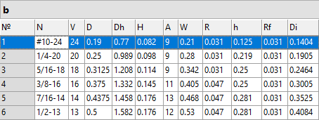
1.If the hole has different versions, it is convenient to use an internal database in which the corresponding standard sizes are entered. In the example, an internal database b has been created, in which the fields of the parameters of the future hole are filled in.

2.A prerequisite is the creation of special variables that will be associated with the parameters of the created element in the Hole command. These variables should be external. It is necessary to create the following variables with the specified values in the new file:
•Is Through – this is the variable that defines the hole type (0 – blind, 1 – through).
The 3D model of any hole fragment shall be created in such a way as to have the hole type (blind, through) change depending on this variable value. The variable value will be determined by the state of the option in the Hole command when inserting the hole. This external variable must necessarily be present in the hole fragment.
•length – this is the variable responsible for the hole depth (when creating a fragment, this variable value can be arbitrary).
When applying a fragment, this variable value will be determined by the system (for a through hole) or by the user in the fragment's external variables dialog (for a blind hole).
You do not have to create this variable (or make it external), if the hole being created can only be blind and its depth cannot be arbitrary, but is rather determined by the standards. In such a case, the depth is uniquely determined by other hole parameters (for example, the diameter, as found in the holes for the positioning screw tips). When applying a hole without the length external variable, the hole type selection options will be inaccessible in the Hole command automenu.
Other necessary variables can be created and named by the user as desired. For example, in the described hole fragment, an additional external variable IsThrough is created. Depending on its value, the hole depth can be increased by the amount defined by another external variable, tempDistCurv. This is necessary in the case when the hole is applied on a curved face (convex or concave) or is directed at an angle to a flat face. When the IsThrough variable value is equal 0 – no depth extension is required, 1 – the depth needs to be extended. A blind hole will be extended by this amount on one side, a through one - on both sides.
3.Creating 3D hole profile
The 3D profile of the hole is created based on 2D constructions on the workplane. Since the hole can be created on a curved face of the model (convex or concave) or directed at an angle to a flat face, it is necessary to provide a protruding part of the hole. Using the tempDistCurv variable, the length of this part is set at both ends of the hole. If the hole is blind (variable IsThrough=0), then the hole depth is L=length. If the hole is through, then L=length+tempDistCurv.
If the hole is inserted on a curved face and additional ejection is required, then the length of this part is set by the value of the tempDistCurv variable.

4.A Rotation operation is created based on the 3D profile. When creating a hole it is also possible to use the Extrusion command. An example is a square hole in the standard library.
It is advisable to create only one operation in the hole fragment file. In the event that the hole has several versions, then its shape should be changed using associative snaps of the construction lines.


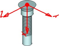
5. When creating a hole, a fragment is inserted using a local coordinate system. It is necessary to create a coordinate system in the hole model that will be used as the default source. The origin point of the coordinate system should belong to the hole axis, and the X axis should be directed inside the hole along its axis. The Use for Fragment Insertion flag should be set in the coordinate system parameters.

6. Since the considered hole is threaded, there is a thread applied to the cylindrical face (the Thread command). The cylindrical face diameter corresponds to the inner thread diameter. The thread parameters (type, diameter, pitch, direction) are bound to variables. To make sure that the thread in the hole appears correctly on a projection, the Thread operation parameters include the Side:Inner parameter.
7. To manage hole parameters, a dialog of control elements is created.
Adding hole to library
In order for the fragment you created to be added to the general list of the Hole command, you need to save it in the \T-FLEX Parametric CAD\Libraries\System\Hole Features\ folder (for metric prototype) or \T-FLEX Parametric CAD\Libraries\System\Hole Features Inch\ folder (for the inch prototype).
You can also create an icon file (*.ico) for your hole file with image sizes of 16x16 (for small icons) and 32x32 (for large icons). The icon file should be named the same as the fragment file (*.grb) and should be in the same folder.