Extrusion |
  
|
Calling the command:
Icon |
Ribbon |
|---|---|
|
3D Model > Create > Extrusion Sheet Metal (3D) > Advanced > Extrusion Workplane > 3D Model > Extrusion Surfaces > Advanced > Extrusion |
Keyboard |
Textual Menu |
<3X> |
Operation > Extrusion |
The command can also be called from the dynamic toolbar or contextual menu for selected contour in the standby mode.

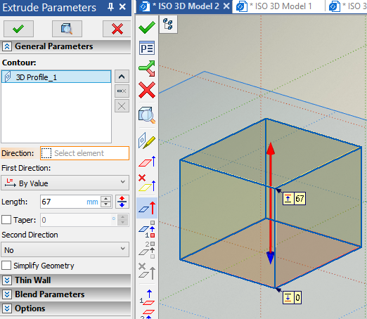
Extrusion operation creates solids by sweeping the shape-defining element (the extrusion contour) along the straight line. Extrusion is a most popular operation across solid modeling systems.
By default extrusion is performed in the normal direction to the base contour surface. Optionally you can select an arbitrary vector as a direction of extrusion.
The command's interface is shown below:

The extrusion contour can be made of wire geometry objects (either flat or 3D), as well as faces and edges belonging to solids and surfaces. You can also select multiple objects of the same type. The result of extruding is a surface or a solid body, depending on the selected contour and thin wall parameters.
The extrusion boundaries and direction can be defined by various means, including usage of existing model elements as a reference. Association with reference object stays active after an operation creation, so extrusion will be recalculated automatically according to reference objects' geometry changes. Additional parameters of operation allow to taper faces and blend edges of resulting body.
Topics in this section: