Boundaries of Extrusion |
  
|
This sub-chapter describes basic principles of assigning extrusion boundaries. The detailed description of operation creation interface can be found in Creating sub-chapter.


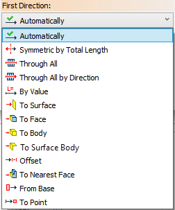
Extrusion boundaries can be assigned using following bounding contidions:
•No
Automatically is the default way of assigning extrusion boundaries. CAD automatically assigns extrusion parameters based on selected inputs (contour and direction). This option allows to associate extrusion Length with length of the selected Direction vector if applicable.
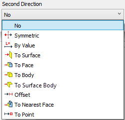
No condition is available for Second Direction only, when First Direction is defined by Automatically, By Value or From Base conditions. This condition disables the extrusion in Second Direction.
Symmetric by Total Length condition makes the extrusion contour equidistant to both ends of the extrusion body. Length parameter value in this case defines the overall length of the whole body.
|
|
Red arrow |
First direction of extrusion |
Red polygon |
Extrusion contour |
100 value |
Length of extrusion in the First Direction (half of the overall length of extrusion set in the Length field of Parameters window) |
Symmetric condition is available for Second Direction only, when First Direction is defined by Automatically or By Value condition. Unlike Symmetric by Total Length in this case overall length of the whole body will be twice higher than Length parameter value.
Through All is one of the ways to define extrusion boundaries using an existing solid body. This condition defines boundaries in both directions at once. It requires using extrusion body in a Boolean operation. Dynamic preview shows an infinite body of extrusion in both directions but size of the operation result is defined by size of the selected existing body. This body is used as the first operand of a Boolean operation. It is useful for creating holes in bodies for instance.
|
|
Blue |
Extrusion contour |
Yellow |
Extrusion body |
Gray |
Target Body for Boolean operation |
Through All by Direction also shows an infinite body of extrusion on the dynamic preview, but it's infinite only in First Direction.
This condition is very similar to the previous one. The difference is using the First Direction of extrusion only. So the resulting body is limited by the extrusion contour on one end and by the body selected as a boundary on another end. This condition also requires using extrusion body in a Boolean operation.
|
|
Blue |
Extrusion contour |
Yellow |
Extrusion body |
Grey |
Target Body for Boolean operation |
Using by Value condition requires setting the Length of extrusion. Using positive length in the First Direction and negative length in the Second Direction allows to create an offset from the extrusion contour. When using opposite sign values for first and second direction length, keep in mind, that their absolute values can not be the same.
|
|
Green rectangle |
Extrusion contour |
100 value |
Extrusion Length in the First Direction |
-50 value |
Extrusion Length in the Second Direction |
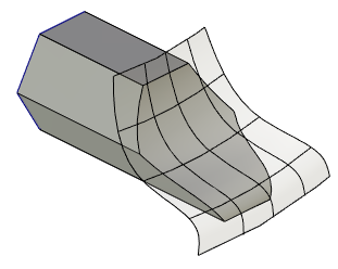
Using To Surface condition allows to select Worksurface, Workplane, generic surface or face as an extrusion boundary. You can also select a flat edge or 3D Profile – in this case a base surface of selected geometry used as a boundary.
Extrusion is limited by the whole surface. Selected boundary surface can be extended automatically if it doesn't fully overlap with extrusion contour. Some complex surfaces, such as an underlying surface of a body face defined by a spline, like those created in the Loft operation, can't be extended. In this case, the surface limits coincide with the limits of its defining object. If selected surface doesn't fully overlap with extrusion contour and can not be extended, extrusion will not be created.
|
|
1 - Face, selected as an extrusion boundary |
Extrusion result |
Additionally you can set an Offset from the selected surface. Positive offset value defines offset from outer side of the selected surface. Not all types of boundary objects allow setting an offset.
|
|
Boundary surface highlighted in green. |
Boundary surface highlighted in green. |
Using To Face condition limits the extrusion body by the selected face. If selected face doesn't fully overlap with extrusion contour, adjoining faces are used for bounding as well. Unlike To Surface condition selected face can not be extended. If it's impossible to fully overlap the extrusion contour by the selected face alone or in combination with other face of the same body, extrusion will not be created. You can select faces belonging not only to solid bodies but to surfaces and 3D profiles as well.
|
|
1 - Boundary face |
Extrusion result |
Using To Body condition limits the extrusion by faces of the selected body. It works in the same way as To Face condition. If several intersections between a boundary body and an extrusion body are possible, operation uses solution nearest to the mouse cursor when clicking the body for selection.
|
Red polygon - Extrusion contour |
Bounding by body is a more robust technique then bounding by a specific face, because different faces may act as the extrusion bounds upon changes in topology of the selected object. (The face selected as a bound at the time of extrusion creation may later shift or disappear altogether.)

Using To Surface Body condition allows to select surface, face or 3D profile as a boundary. Unlike other conditions a surface consisting of several faces can be selected as a whole. If several intersections between a boundary surface and an extrusion body are possible, operation uses solution nearest to the mouse cursor when clicking the surface for selection. Unlike To Surface condition the selected boundary will not be extended when it doesn't fully overlap with the extrusion contour.

Unlike By Value when using Offset condition First and Second Direction vectors have the same direction. So if you want to achieve the same result as in the illustration to the By Value condition, you need to set positive Offset values in both directions. Second Direction offset should always be lower than First Direction offset.

To Nearest Face condition is a special case of To Body condition. This condition always uses the first intersection between extrusion body and boundary body in selected direction. Keep in mind following rules when using this condition:
1) The specified extrusion boundaries (at least one of which is the To Nearest Face) must lay in opposite directions from the original contour. An exception from this rule is the case when the second extrusion boundary is defined using Offset condition.
2) The boundary body must lay in the First Direction, when it defines the first boundary, and in the Second Direction, when defining the second boundary.
|
|
Extrusion contour highlighted in blue, boundary body for both directions highlighted in gray. |
Operation result |
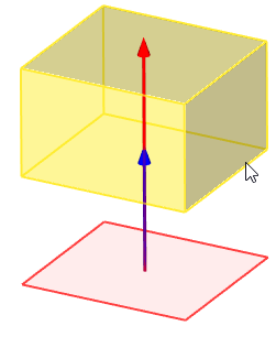
From Base condition allows to set the extrusion Length in the First Direction not from contour but from base when extruding a flat contour. A point or a plane parallel to the contour plane can be used as a base. In this case the Length value defines distance between base and end of the extrusion body.
|
|
|
Length 0 mm |
Length 300 mm |
Length -150 mm |
You can use a point as an extrusion boundary in first or second direction when extruding a flat contour. Point can be defined by 3D node, vertex, edge midpoint or other 3D objects.
|
1 - Extrusion contour 2 - Boundary point |