Additional Options for Extrusion |
  
|
Tapers can be applied automatically on the side faces while creating an extrusion. All side faces of the body being created are slanted from the original position by the specified angle. If you want to apply a taper, enable Taper checkbox under corresponding Length or Offset value (depending on the selected boundaries) in the General Parameters tab of the Parameters window. Taper angle value can be set in the field on the right side of this flag.
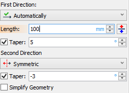
The direction of tapering depends on the specified angle and body type. If the resulting extrusion is a solid body then positive angle values correspond to tapering toward the inside of the body. For the opposite result, specify a negative tapering angle.
|
||
No taper |
Positive taper |
Negative taper |
When creating a surface, the choice of taper direction is left out to the system. If the system choice is different from the desired, simply change the angle sign.
The taper angle can be defined either separately for each extrusion direction (if the extrusion length was defined by a numerical value or direction vector length), or once for the whole extrusion (if the extrusion length was defined by specifying bounds).
|
|
Uniform taper for the whole extrusion |
Separate tapers for each direction |
Thin Wall parameters can be set in the eponymous tab of the Parameters window.
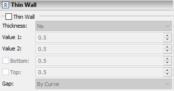
Enabling Thin Wall checkbox activates drop-down menu for selecting Thickness application direction. This checkbox can only be enabled when extruding flat contours.
There are following thickness application directions available:
•No
•Outward
•Inward
•Symmetric
•Double sided
Selecting No in the drop-down menu leads to creation of a zero-thickness surface.
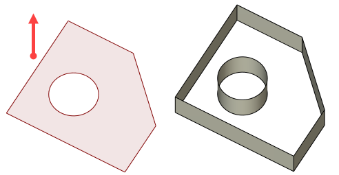
Extrusion contour |
Extrusion result with Thin Wall checkbox enabled and No thickness application direction selected |
Selecting Outward, Inward or Symmetric activates the thickness Value 1 field and the operation yields a solid body with a thickness applied to selected direction. The resulting body is similar to Shell operation result.
Selecting Double sided activates thickness Value 1 and Value 2 fields, giving the ability to specify different values for outward and inward thickness. Value 1 - outward, Value 2 - inward.
|
|||
Outward |
Inward |
Symmetric |
Double sided |
The new faces in the thin-wall body are created by extruding an offset contour of the original one. The shape of the faces depends on the choice of handling the gaps when creating an offset contour. Following choices for gap handling become available in the Gap drop-down menu after selecting the thickness application direction:
Round – The free ends of the neighboring offset curves are connected by fillets.
By line – The offset curves of the original contour are extended at their free ends by tangent straight line segments.
By curve – The offset curves of the original contour are prolonged until intersect.
|
||
Round |
By line |
By curve |
Faces parallel to the contour plane are excluded from the result of Thin Wall extrusion by default. You can include them manually by enabling corresponding checkboxes. Enabling Bottom checkbox includes face on the end of the second direction of extrusion. Enabling Top checkbox includes face on the end of the first direction of extrusion. Bottom and Top thickness values can be set independently of other extrusion's elements thickness.
This feature is not available when boundaries are specified for the extrusion or when using open contour.
|
|
Thin Wall with Top and Bottom disabled |
Thin Wall with Top and Bottom disabled (section view) |
|
|
Thin Wall with Top and Bottom enabled |
Thin Wall with Top and Bottom enabled (section view) |
Blend Parameters can be set in the eponymous tab of the Parameters window.
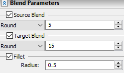
Enabling Fillet checkbox activates blending of extrusion side edges. Side edges can only be blended by a round fillet. Fillet Radius can be set in the corresponding field. You can also add blending of the top and bottom faces if the operation yields a solid body. Enabling Target Blend checkbox activates blending on the first direction ending face. Enabling Source Blend checkbox activates blending on the second direction ending face. You can choose between Chamfer and Round (fillet) types of target and source blend in the drop-down menu. Chamfer size or Round fillet radius can be set in the field on the right side of the drop-down.
Source Blend and Target Blend checkboxes are not available for the Thin Wall with No thickness. Enabling Source Blend and Target Blend checkboxes for the Thin Wall with some thickness blends both inner and outer contour edges of the corresponding face. Operation can not be completed if source or target blend size exceeds half of the overall (inward plus outward) thickness of the Thin Wall.
|
||
Target Blend (Chamfer type) enabled for the Thin Wall with defined thickness |
Source Blend (Round type) enabled |
Fillet enabled for the Thin Wall with No thickness |
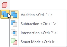
Using created body in Boolean operation
Options for Boolean operation creation are available in lower part of the automenu.
Information about these options can be found in the Using Boolean Operation when Creating Other Operations section.
