Main Concepts of Extrusion |
  
|
Main Concepts of Extrusion |
|
This sub-chapter describes basic principles of extrusion geometry creation. The detailed description of operation creation interface can be found in Creating and Additional Features sub-chapters.
The extrusion contour can be made of wire geometry objects (both flat and 3D), as well as faces and edges belonging to solids and surfaces. You can also select multiple objects of the same type. By default operation yields a surface or a solid body, depending on the selected contour:
•a single closed 3D profile or a single face yields a solid body;
•multiple closed 3D profiles or multiple faces yield a single solid body which visually consists of multiple parts;
•a rib yields a surface, no matter if rib closed or not;
•a single open contour yields a surface;
•multiple open contours yield a surface, even if the combination of selected objects looks like a closed contour.
However, you can create surfaces from contours that yield solids and vice versa, using Thin Wall parameters.

The trajectory of sweeping the contour for extrusion is defined by the extrusion direction. By default extrusion direction is set as the normal to the original contour surface. Optionally you can select an arbitrary vector as a direction.
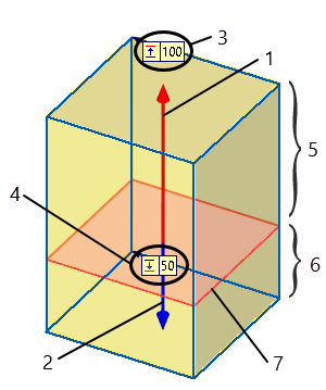
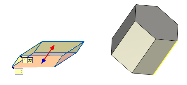
In either case, there are first and second directions of sweeping the contour. The First Direction coincides with the normal direction or the extrusion vector. The Second Direction is opposite to the first one. Two-sided extrusion is also supported, in which the contour is swept in both directions. By default, the system creates extrusion in the first direction.
|
|
1 |
First direction of extrusion |
2 |
Second direction of extrusion |
3 |
Length of extrusion in first direction |
4 |
Length of extrusion in second direction |
5 |
Preview of the first direction extrusion result |
6 |
Preview of the second direction extrusion result |
7 |
Extrusion contour |
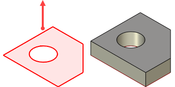
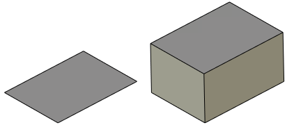
Extruding along the normal is the system default when selected contour allows to calculate normal direction. Each point on the contour is swept along a separate line defined by the normal direction to the contour surface at the point. In this case, extrusion can be described as an offset from the original contour defined by the specified length of the extrusion.
In real life, flat contours are extruded most often, with the same normal direction at all points of the contour. For practical purposes, one can think of the flat contour in this case being translated parallel to its original position along one common line defined by the single normal to the contour plane. Therefore, extrusion normal to the flat contour can be viewed as a special case of extruding along an arbitrary vector.

Extrusion of a non-flat contour
Extrusion of a flat contour
Extruding along an arbitrary vector
When the extrusion direction can't be defined by the normal (for example, if a non-flat wire contour was selected) or extrusion is desired in a specific direction, then its definition may include an arbitrary direction vector.
The vector of the extrusion direction can be defined in two ways:
1) By specifying a pair of 3D points (the vector start and end);
2) By selecting some element of the 3D model suitable for defining a vector in the desired direction (regardless of the length).
Two 3D points define the start and end of the extrusion direction vector. 3D points can be defined by 3D nodes and vertices. One can also select other elements defining the desired point. For example, one can select an edge – in this case, the edge midpoint will be used as the 3D point. Selecting a coordinate system defines the point at the origin. Selection of a face, which is part of a sphere or torus – yields the point at the center of the sphere/torus, and so on.
|
|
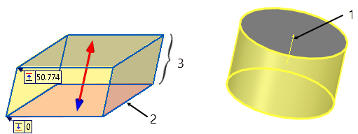
1 |
Extrusion direction vector (not displayed in the 3D scene) |
2 |
Start point |
3 |
End point |
4 |
Extrusion contour |
5 |
Extrusion result |
In the latter approach, the selected 3D object defines the vector of extrusion direction. The suitable kinds of objects are flat curved edges, workplanes, flat faces, arbitrary-shaped surfaces (the direction is determined as the normal to the selected element), straight edges (the vector coincides with the selected edge), coordinate systems (the direction is one of the axes), faces/surfaces that are part of a cylinder or a torus (the direction of the vector is the direction of the face/surface axis). It is possible to select vector using single point only (if it lays on some surface). In this case a normal direction to surface at selected point is used as a vector.
|
|
1 |
The axis of the cylindrical face defines direction of the extrusion vector |
2 |
Extrusion contour |
3 |
Extrusion result |
The length of an extrusion can be specified in one of the three ways:
1) By the length of the defining vector of the extrusion direction;
2) By an arbitrary numerical value, measured from the original contour position;
3) By extrusion bounds;
4) By an offset from bounds.
Defining extrusion length by length of direction vector
The extrusion length can be derived from the length of the defining vector of the extrusion direction in the cases when the direction is defined by two 3D points or a straight edge. The length of the extrusion vector in this case is defined by the distance between the specified points or the length of the selected edge. Extruding is performed from the original contour position in forward direction by the length equal to the vector length. The length of extruding in the reverse direction, if necessary, can be defined by an arbitrary number or set equal to the length of extruding in the forward direction.

Defining extrusion length by numerical value
Regardless of the ways of defining extrusion direction, the extrusion length in the forward direction (from the original contour position) can be defined by an arbitrary numerical value. The extrusion length in the reverse direction, if necessary, is defined by an arbitrary numerical value or is set equal to the length of extruding in the forward direction.
Defining extrusion length by extrusion boundaries
When specifying the extrusion length using boundaries, the extrusion is performed from one boundary to another.
More information about extrusion boundaries can be found in Boundaries chapter.
Defining extrusion length as an offset from a boundary
For some of the boundary types it's possible to define an offset in forward or reverse direction from the object selected as boundary.
|
|
|
Extrusion to surface without offset |
Extrusion to surface with a reverse offset |
Extrusion to surface with a forward offset |