Create Extrusion |
  
|
Creating an extrusion operation
The Automenu and the Parameters window are used together in the command. These work together and enhance each other. The state of the automenu depends on the current step in defining the operation and on the purpose and type of the objects being selected.
Following steps should be done to create an operation:
2.Set Common parameters of operation (non-mandatory action)
3.Select the extrusion contour
4.Define the extrusion direction (non-mandatory action if using normal direction).
5.Define the extrusion boundaries (non-mandatory action).
6.Set Length or Offset values (non-mandatory action in some cases).
7.Set Taper, Thin Wall, Blend, Boolean operation parameters (non-mandatory actions).
8.Use Preview of the operation result (non-mandatory action).
9.Finish input ![]() .
.
Following options become available in the automenu after calling the extrusion command:
|
<W> |
Draw Profile |
|
<R> |
Select Contour |
|
<H> |
Cancel contour selection |
|
<D> |
Select Direction |
|
<F> |
Select starting Point of Extrusion |
|
<S> |
Select ending Point of Extrusion |
|
<K> |
Reset Direction selection |
|
<T> |
Select 1st limit of extrusion |
|
<B> |
Select 2nd limit of extrusion |
|
<U> |
Reset Bounds selection |
|
<N> |
Select Starting Point of Extrusion |
|
<L> |
Select Plane setting starting position of Extrusion |
|
<O> |
Cancel selection of Extrusion Base |
|
<Ctrl+T> |
Select Target Body for Boolean |
|
<Ctrl+B> |
Boolean operation mode |
Selecting the extrusion contour
When creating the extrusion operation, it is necessary to define the extrusion contour. Upon calling the command, the following option automatically activates in the automenu:
|
<R> |
Select contour |
This option's activation enables filters for selecting 3D elements allowed as an extrusion contour (3D profiles, operations, faces, edges, loops and 3D paths) on the Filter Toolbar. When selecting elements, pay attention to active filters.
To define the extrusion contour, move the cursor over the desired element in the 3D window. The pointed at element will be pre-highlighted, and the cursor gain a tooltip with the element name. Click ![]() to select.
to select.
3D profiles based on hatches can be selected by picking the original hatch in the 2D window.
The Contour filed in the General Parameters tab of the Parameters window activates in conjunction with the activation of the Select contour option in the Automenu. Upon selecting a contour this field will contain a name of a selected element and an icon depicting a type of a selected element. Upon multiple contours selection only number of elements is shown as well as an icon depicting multiple elements. Right side of the Contour contains buttons allowing you to ![]() Clear the selection and
Clear the selection and ![]() Expand list of selected elements.
Expand list of selected elements. ![]() Clear button is also available in other fields for geometrical elements selection.
Clear button is also available in other fields for geometrical elements selection.
![]()
Clicking the ![]() Expand button changes the Contour field layout. Left side of the field will contain the list of all selected contours. The
Expand button changes the Contour field layout. Left side of the field will contain the list of all selected contours. The ![]() Expand button on the right side of the field will be replaced by the
Expand button on the right side of the field will be replaced by the ![]() Collapse button which allows you to switch to previous layout. The
Collapse button which allows you to switch to previous layout. The ![]() Delete Element from the List button also appears allowing you to delete the selected (highlighted in blue in the list) contour. Click
Delete Element from the List button also appears allowing you to delete the selected (highlighted in blue in the list) contour. Click ![]() on an element in the list if you need to select it.
on an element in the list if you need to select it.
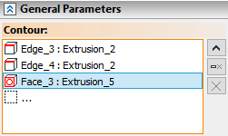
You can also call the new profile creation command using the following automenu option:
|
<W> |
Draw Profile |
Upon finishing the new profile creation it will be selected as an extrusion contour automatically.
Keep in mind that all extrusion parameters defined before the new profile creation will be reset to default.
Upon selecting an extrusion contour the following option will be available in the automenu:
|
<H> |
Cancel contour selection |
Elements selected as an extrusion contour are highlighted in red in the 3D scene throughout defining an operation parameters.
Calling the command with automatic contour selection
A slick way of handling an extrusion is calling the command with automatic selection of an extrusion contour.
Enter the Draw on workplane mode and draw an extrusion contour.
Then, without leaving the active workplane mode, call the Extrusion command. The system will then automatically create a 3D profile based on the Continuous type graphic lines or a hatch, and will select it as an extrusion contour. If you'll draw on the same workplane again, automatic contour selection will work for newly created contours only (new color).
Defining the extrusion direction
Upon selecting a sheet or flat wire contour, the system automatically offers to create an extrusion in the direction normal to contour plane. This is indicated by the preview of the resulting body, displayed on the 3D scene. There is no need in this case for defining the extrusion direction. The user can alter the kind of extrusion simply by defining a different extrusion direction by specifying a direction vector.
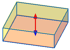
If a preview is not displayed in the 3D scene, extrusion in the normal direction can't be created from this contour.
The following automenu option allows to define an extrusion direction vector by a 3D model element:
|
<D> |
Select Direction |
This option allows to select a 3D element suitable for defining an extrusion direction vector. This option's activation enables filters for selecting 3D elements allowed as an extrusion direction on the Filter Toolbar. When selecting elements, pay attention to active filters. Selected element will be shown in the Direction field in the General Parameters tab of the Parameters window.
![]()
The following automenu options allows to define an extrusion direction vector by two 3D points (activate sequentially):
|
<F> |
Select starting Point of Extrusion |
|
<S> |
Select ending Point of Extrusion |
This option's activation enables filters for selecting 3D elements allowed as an extrusion direction on the Filter Toolbar. When selecting elements, pay attention to active filters. A 3D point can be defined by selecting a 3D node, a vertex on a body, profile or path. Besides, selecting an edge yields the edge midpoint as the 3D point (for straight edges) or the center (for edges that are full circles, arcs or ellipses). Selecting a face that is part of a sphere or torus yields the sphere/torus center as the point. A coordinate system selection yields the origin as the 3D point. If you define an extrusion direction by two points, the Direction field in the General Parameters tab of the Parameters window will be replaced by two new fields: First Point and Second Point.
![]()
You can also reverse the direction vector by clicking the ![]() Reverse Direction button located on the right side of the Length or Offset fields (depending on the selected bounding condition) in the General Parameters tab of the Parameters window.
Reverse Direction button located on the right side of the Length or Offset fields (depending on the selected bounding condition) in the General Parameters tab of the Parameters window.
The last option for the direction defining in the automenu cancels the vector selection:
|
<K> |
Reset Direction selection |
Elements selected for defining an extrusion direction are highlighted in yellow in the 3D scene throughout defining an operation parameters.
You can also define the extrusion direction using manipulators.
Defining the extrusion boundaries
The extrusion bounding condition can be selected in the General Parameters tab of the Parameters window. This tab contains two groups of parameters - First Direction and Second Direction. Each group contains the drop-down where you can choose a bounding condition for the respective direction.
The names of the parameter groups (First Direction and Second Direction) for specifying boundaries are essentially arbitrary. The boundaries positions are generally not related to the extrusion directions. The exception here is the bounding condition To Nearest Face that is defined for a particular extrusion direction.
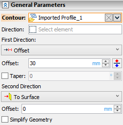
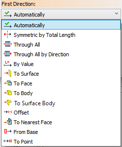
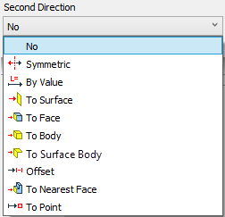
Automenu options for selecting boundaries are activated depending on the selected bounding condition.
Automatically, Symmetric and Symmetric by Total Length conditions do not require boundaries selection, so you can move on to defining a Length. Through All and Through All by Direction conditions do not require either boundaries or length, but do require defining a Boolean operation parameters.
Selecting boundaries using From Base condition uses unique interface.
Selecting the bounding condition activates one of the following options in the automenu (depending on whether the first or second direction being bounded):
|
<T> |
Select 1st limit of extrusion |
|
<B> |
Select 2nd limit of extrusion |
These options are used for selecting 3D elements as boundaries. This options' activation enables filters for selecting 3D elements allowed as a boundary on the Filter Toolbar. When selecting elements, pay attention to active filters. Availability of certain filters depends on the selected bounding condition.
The last option in this automenu group cancels the selection. Depending on the state of the command, one of the following options available:
|
<U> |
Discard 1st extrusion limit |
|
<U> |
Discard 2nd extrusion limit |
|
<U> |
Reset Bounds selection |
The option ![]() is available while defining the first boundary (under the active option
is available while defining the first boundary (under the active option ![]() ). The option
). The option ![]() is available while defining the second boundary (under the active option
is available while defining the second boundary (under the active option ![]() ). In other states of the command (for example, under the option of contour or direction selection), the option
). In other states of the command (for example, under the option of contour or direction selection), the option ![]() is displayed allowing to cancel both boundaries selection at once.
is displayed allowing to cancel both boundaries selection at once.
Elements selected as extrusion boundaries are highlighted in green in the 3D scene throughout defining an operation parameters.
Some types of boundaries can also be selected using manipulators.
Following options are available in the automenu for selecting a base:
|
<N> |
Select Starting Point of Extrusion |
|
<L> |
Select Plane setting starting position of Extrusion |
This options' activation enables filters for selecting 3D elements allowed as a base on the Filter Toolbar. When selecting elements, pay attention to active filters.
First option is activated automatically upon selecting From Base bounding condition. You can switch to second option by clicking ![]() on it if necessary. Both options can also be activated by clicking
on it if necessary. Both options can also be activated by clicking ![]() on them without selecting a bounding condition. In this case From Base condition will be selected automatically upon selection of a base in 3D scene.
on them without selecting a bounding condition. In this case From Base condition will be selected automatically upon selection of a base in 3D scene.
You can cancel base selection using following automenu option:
|
<O> |
Cancel selection of Extrusion Base |
Defining the extrusion length or offset
The extrusion Length value can be set in the General Parameters tab of the Parameters window. Defining a Length value depends on the selected bounding condition. For some bounding conditions Length values should be set separately for each direction (First and Second), other require Length value for the First Direction only. Some bounding conditions use Offset value instead of Length.
You can also set Length or Offset values using manipulators.
Defining extrusion length by direction vector length or by numerical value
The default bounding condition for extruding in the First Direction is Automatically. It allows the system to automatically choose a means of defining the extrusion length in the first direction (depending on the way of defining the extrusion direction).
When defining the extrusion direction by a vector, the system tries to define the extrusion length in the first direction by the vector length. This is possible only when the vector is defined by two 3D points or a straight edge. Value displayed in the Length field reflects the vector length value. To override this mode, you can force the extrusion length input mode (in the first direction) by a numerical value. To do this, simply enter the new value into the Length field or change length using manipulators.
When defining the direction vector by other means (for example, by axis of a cylindrical face or normal to a surface), as well as in the case using direction normal to contour plane, the extrusion length can't be defined by the length of the direction vector. In this case Length value will be set to default (10 mm), which you change manually.

By default, extruding is not performed in the second direction. No bounding condition applied in this case. The input boxes of the extrusion length and taper in the second direction are inaccessible.

To perform extruding in the second direction, select another bounding condition from the drop-down.
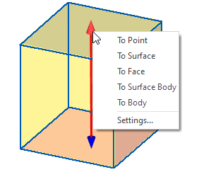
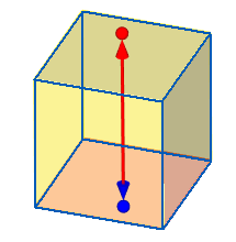
To specify the length and also the direction of the extrusion, it is possible to use the special arrow-shaped manipulators in the 3D scene. Red arrow represents First Direction of extrusion, blue arrow - Second Direction. If you don't see manipulators make sure that they are enabled. Under some bounding conditions manipulators are displayed only after boundary selection. Under Through All and Through All by Direction conditions manipulators are not available. Under Symmetric and Symmetric by Total Length conditions manipulators are only available for first direction.
Context Menu of the Extrusion Manipulators
Clicking ![]() on the tip (cone) of the manipulator arrow invokes the context menu, where you can choose some of the bounding condition for selected direction::
on the tip (cone) of the manipulator arrow invokes the context menu, where you can choose some of the bounding condition for selected direction::
•To Point;
•To Surface;
•To Face;
•To Surface Body;
•To Body;
or open the Manipulator Settings window.
Clicking ![]() one of the bounding conditions in the context menu sets the corresponding condition in the Parameters window's drop-down for selected direction and activates boundary selection mode.
one of the bounding conditions in the context menu sets the corresponding condition in the Parameters window's drop-down for selected direction and activates boundary selection mode.
Clicking ![]() on the axis of the manipulator arrow or on the ball of the end point manipulator invokes short context menu where the only option available is to open the Manipulator Settings.
on the axis of the manipulator arrow or on the ball of the end point manipulator invokes short context menu where the only option available is to open the Manipulator Settings.
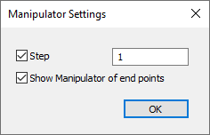
Extrusion Manipulators Settings
There are two checkboxes in the Manipulator Settings window:
•Enabling the Step checkbox overrides the default step value by the custom value which you can set in the field on the right side of the flag. Step is responsible for the manipulator position change increment upon dragging it while holding the ![]()
•Enabling Show Manipulator of end points checkbox enables ball-shaped manipulators near tips of arrows. It is disabled by default.
Manipulator position change increment depends on a view scale in the 3D scene window. Zooming in or out at some point will lead to 10 times change of the increment. Increment is measured in units, which are set in the right part of the Length or Offset field.
Extrusion Manipulators usage
Clicking ![]() on the tip (cone) of the manipulator arrow makes cone move along the extrusion direction vector in accordance with the cursor movement until
on the tip (cone) of the manipulator arrow makes cone move along the extrusion direction vector in accordance with the cursor movement until ![]() is clicked for the second time.
is clicked for the second time.
Second ![]() click:
click:
•on a 3D point of an existing geometry selects this point as an extrusion boundary and automatically selects To Point bounding condition for this direction of extrusion;
•on any other location of the 3D scene (if Offset bounding condition was not selected) selects By Value bounding condition for this direction of extrusion and sets Length value corresponding to the current position of the cone;
•on any other location of the 3D scene (if Offset bounding condition was selected) sets Offset value corresponding to the current position of the cone;
Dragging the mouse while holding ![]() on the tip (cone) of the manipulator arrow leads to Length value change (or Offset value if Offset bounding condition was selected) in accordance with the cursor movement. Setting length using this method automatically selects By Value bounding condition for this direction of extrusion. It is not necessary to click directly on the manipulator cone. Move the cursor over the end face (parallel to the extrusion contour) of the wire-frame preview of the operation result. An icon
on the tip (cone) of the manipulator arrow leads to Length value change (or Offset value if Offset bounding condition was selected) in accordance with the cursor movement. Setting length using this method automatically selects By Value bounding condition for this direction of extrusion. It is not necessary to click directly on the manipulator cone. Move the cursor over the end face (parallel to the extrusion contour) of the wire-frame preview of the operation result. An icon ![]() (for First Direction) or
(for First Direction) or ![]() (for Second Direction) will appear near the cursor. As long as icon is displayed dragging the mouse while holding
(for Second Direction) will appear near the cursor. As long as icon is displayed dragging the mouse while holding ![]() works in the same way as when you do it directly on the manipulator cone. These icons might be unavailable in some cases.
works in the same way as when you do it directly on the manipulator cone. These icons might be unavailable in some cases.
.
Clicking ![]() on the shaft of the manipulator arrow activates mode for selecting an extrusion direction vector. Move the cursor over a desired object. The appearance of the manipulator will change - it shows the preview of an extrusion in this direction. If you are satisfied with a result, click
on the shaft of the manipulator arrow activates mode for selecting an extrusion direction vector. Move the cursor over a desired object. The appearance of the manipulator will change - it shows the preview of an extrusion in this direction. If you are satisfied with a result, click ![]() on an object to select it as an extrusion direction.
on an object to select it as an extrusion direction.
Clicking ![]() on the ball of the end point manipulator activates mode for selecting a starting or ending point of the extrusion direction vector. move cursor over the desired point. The appearance of the manipulator will change - it shows the preview of an extrusion in this direction. If you are satisfied with a result, click
on the ball of the end point manipulator activates mode for selecting a starting or ending point of the extrusion direction vector. move cursor over the desired point. The appearance of the manipulator will change - it shows the preview of an extrusion in this direction. If you are satisfied with a result, click ![]() on a point and it will be selected as a starting or ending point (depending on which ball manipulator you are using) of an extrusion direction vector. Second point can be selected in the same way. You don't have to select both points using the manipulators. Each point can be selected using different methods.
on a point and it will be selected as a starting or ending point (depending on which ball manipulator you are using) of an extrusion direction vector. Second point can be selected in the same way. You don't have to select both points using the manipulators. Each point can be selected using different methods.
See also:
•Using created body in Boolean operation
•Common options of solid 3D modeling operations
•Common Parameters of 3D Elements