Control |
  
|
To create a dialog box, use the Control command. It can be called by one of the following means:
Icon |
Ribbon |
|---|---|
|
Draw > Additional > Control Sheet Metal (2D) > Additional > Control Parameters > GUI Control > Control |
Keyboard |
Textual Menu |
<TR> |
Draw > Control |
When working with parametric models and while building an assembly, the user often needs to edit the values of external variables of the models being designed or fragments being a part of an assembly. The T-FLEX CAD general variable editor can be used for handling external variables. However, it is much easier and simpler to work with specially created custom dialogs containing Windows-native tools (input boxes, drop-down lists, "Yes/No" switches, etc.).
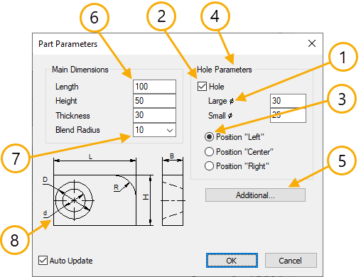
A custom dialog provides a quite convenient and easy way of editing external variables in a parametric model. It is developed by the user when creating a model or fragment. Special T-FLEX CAD system elements, namely, control elements, are used for creating a custom dialog. When creating a dialog, the developer can make it clear and easy to use by adding necessary explanations and comments in the dialog and by structuring the input of the model parameters in a most comprehensible way.
In the future, a custom dialog will be called instead of the general variable editor whenever necessary to edit external variables of a given model or fragment. A custom dialog will be coming up upon calling the command for modifying external variables, Parameters > Model, in the current document and in the parameters window when inserting the current document as a fragment.
General information and types of control elements
T-FLEX CAD system supports the following types of control elements for use in the custom dialogs.
The control elements Static Text, Frame and Group Box are not related to any variables and are used for making a clear dialog layout and providing hints.
•Static Text is a text string positioned in the specified area of the dialog box.
•Frame is a rectangular frame or rectangular area of the specified color. By default, this is a black frame or a rectangle of the background color.
•Group Box is a frame with a text aligned with the top border of the box.
The two last elements are used for enhancing and structuring the visual appearance of control elements in the dialog box. Other visual means can also be used for this purpose.

Other elements – Edit Box, Button, Combo Box, Check Box, Radio Button, Preview - are related to variables or the model pages and is intended for manipulating those in certain ways.
Edit Box is a rectangular field for editing the value of the variables associated with this box. Edit box is used for variables without lists of predefined values. It is possible to work in a mode when the displayed value cannot be edited (in this case, in the Edit Box field the value of the connected to this field variable will be shown but this value will not be possible to modify).
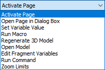
Button. A button defines the sequence of actions performed upon pressing it. Such actions can be:

For more information, see the section describing creation of controls.
Combo Box is a rectangular field with a pulldown list button ![]() on the right. A combo box is used for modifying a variable value when there is a predefined list of values. The element parameters define whether it is possible to edit the input value.
on the right. A combo box is used for modifying a variable value when there is a predefined list of values. The element parameters define whether it is possible to edit the input value.
Check Box switches between the two values of the selected variable. The particular value depends on the check box state.
Radio Button switches between the variable values defined in the radio group parameters. Radio buttons can be conveniently used for variables with several fixed choices of values. (In the case of just two choices, Check Box can be used instead.) In this case, a radio group of switches is created for the variable, each representing one of its values.
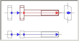
The custom dialogs allow creation of Preview controls.

Such an element allows displaying a preview pane for a page per the specified fixing vector in the dialog box for editing the fragment external variables. Preview is not available in the dialogs called by the command Parameters > External Variables.
When creating a dialog box, besides the control elements proper, you can use any drawing elements: nodes, construction lines, images, pictures, etc. Construction lines and nodes are not displayed as part of the dialog box window, however, those can be used for precise positioning of control elements when creating complicated dialogs.
Graphic elements and pictures can be used as additional detailing elements in the dialog box along with the standard control elements, such as Frame, Group Box, Static Text. Those elements can be used, for example, for creating a simplified parametric drawing on the page of the dialog box. In this way, the user can evaluate the changes made to the model parameters by this drawing.
Topics in this section: