Dependence of 3D Fragments on Assembly in Top-down Design |
  
|
When designing "Top-down", the fragments should depend on the assembly. In T-FLEX CAD, there are three mechanisms by which such a relation can be made:
•Reference Element,
•Geometric Parameter,
•External Variable.
External variables and geometric parameters of adaptive fragments can be used in the "Bottom-up" design, and are not a new feature of T-FLEX CAD. The use of external variables and adaptive fragments is described in the appropriate subsections: Parametric Relation definition and Adaptive 3D Fragments.
Creating a Reference Element is a feature of T-FLEX CAD that is specifically designed to provide link from assembly to fragments (or directly between fragments). The reference element can be placed in the geometric parameter of the fragment – then such a fragment becomes adaptive.
The presence of a Reference Element in the Geometric Parameter makes it possible to receive a new adaptive fragment variation when changing the geometry in the assembly, without updating the reference elements in the fragment files.
Consider the possible combinations of reference elements and geometric parameters of the fragments in the "Top-down" design.
•The fragment is non-adaptive, without reference elements (a frequent case when a fragment is inserted into an assembly on a "Bottom-up" design basis with the use of LCS).
•The fragment is adaptive, containing reference elements in geometric parameters (a frequent case when working with fragments of the first level).
•Adaptive fragment containing geometric parameters (outdated methods of detail unloading)
•Adaptive fragment containing reference elements both in geometric parameters and reference elements not in geometric parameters (a common case when working with fragments in the context of different assemblies).
•The fragment is non-adaptive, containing reference elements (a frequent case when working with fragments of the second and deeper levels).
In the Assembly Structure and 3D Model windows, fragments with geometric parameters are specified using a special icon.
The presence or absence of geometric parameters of fragments of the second and lower levels cannot be seen in the Assembly Structure window. To do this, use the 3D model window, or open a fragment in the context of the subassembly for which it is a fragment of the first level.
|
Non-adaptive Fragment or Fragment Containing Only Reference Elements |
|
Adaptive fragment containing geometric parameters or reference elements in geometric parameters |
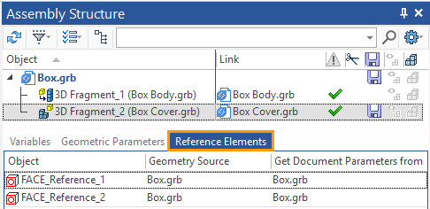
External variables of the fragment, its geometrical parameters and reference elements can be seen in the Assembly Structure window.


If the fragment was not created as adaptive, it can be made adaptive by adding a geometric parameter. If the fragment was created without reference elements, you can add them by opening the fragment in the context of the assembly and using theReference Element command. If a fragment does not have reference elements in geometric parameters, you can create them by opening the fragment in the context of the assembly in which it is a fragment of the first level and using the Reference Element command. Any fragment can be made non–adaptive. To do so, you need to delete all its geometric parameters.
In other words, we can change the variants of the fragment dependence on the assembly.
Reference elements-cannot be removed, because they are based on the body of the fragment.
You can prevent a reference element from being updated (either when it is created, or later through its context menu in the 3D Model window).In this case the fragment will behave as a fragment without a reference element, since further borrowing of the source geometry for the reference will be prohibited.
A non-adaptive fragments without reference elements are files with geometry elements (or even without them) that do not have Geometric Parameters.
You can create a non-adaptive fragment without reference elements ![]() in the following ways:
in the following ways:
•Using the Create a 3D fragment command without using reference elements or other geometric parameters of the fragment.
•Use the Detail > Create command with the Create Fragment option. A construction should not depend on other constructions in the assembly.
• Insert 3D Fragment is a standard command when designing "Bottom-up".
Non-adaptive fragments without reference elements should be created only if the part is not going to change. The created fragment should be the main one in the assembly, all other fragments should depend on it, and the fragment itself should not depend on changes in other fragments. In the case when changes in the assembly are made using "Bottom-up" design.The fragment is adaptive and contains reference elements in geometric parameters. Such a fragment can be created if the reference element automatically is automatically added to the geometric parameters – detailed information is given in the Reference Element in Geometric Parameters section.
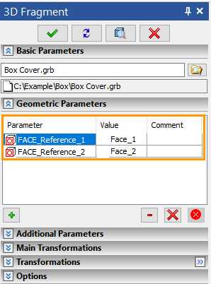
The geometric parameters of any adaptive fragment can be seen in the parameters window of the 3D Fragment command. To call this command for an already created fragment, you can select ![]() Edit from the fragment context menu.
Edit from the fragment context menu.

The fragment is adaptive, containing geometrical parameters. This type of fragment provides a link only between the assembly and the first level fragment.
When designing "Top-down", the primary binding element of the assembly is the reference element. You can also use other tools to link a fragment to an assembly: variables and geometric parameters. As mentioned above, a reference element can be a geometric parameter, but in this case we consider a fragment that does not contain reference elements at all, but contains only geometric parameters. The case when during "Top-down" designing the fragment has no reference elements, but has geometric parameters can occur if:
•the user select the last two options of the Detail > Unload command;
•the user calls the Create 3D Fragment command, but does not create reference elements, and using the Adaptive Fragment command, creates geometric parameters for the fragment;
•the user uses the Bottom-up design principle and inserts a fragment (Insert 3D Fragment) that is created as an adaptive Fragment (Adaptive Fragment).
The adaptive fragment is adaptive and contains reference elements in the geometric parameters and in the reference elements not in the geometric parameters. Fragments, in which part of the reference elements were in the geometric parameters, and part is not is a possible case. Such fragments can be created as follows.
•If you create reference elements for a fragment in the context of different assemblies, one of which is a fragment of the first level.
•When you edit a fragment in the context of an assembly for which the fragment is a first-level fragment, you specify Geometry Source in the assembly for part of the reference elements, and specify Geometry Source in the assembly for part in the fragments.
•When you create a reference element in a context of any other assembly (it is not the assembly, where the fragment was created) for a fragment received using the Detail > Create command with Create Adaptive Fragment option.
You must remember that adaptive fragments change their geometry according to the value of the geometric parameters in the assembly, so the execution of the geometry in the fragment file and the execution of the fragment in the assembly may differ. If you want a fragment that has a reference element not in geometric parameters, to change its geometry in the assembly, you must update the reference element in the fragment file. Accordingly, those reference elements that are in the geometric parameters of the fragment will change the geometry of the fragment without updating the references in the fragment file, and those that are not in the geometric parameters will change the geometry of the fragment only after the update.
If a fragment contains a part of the references in the geometric parameters, and some – out of geometrical parameters, it should be understood that simultaneously two different communication methods of a fragment and the assembly are used. If you change the source geometry of reference elements you should take care of the changes order and order of the reference elements updates .
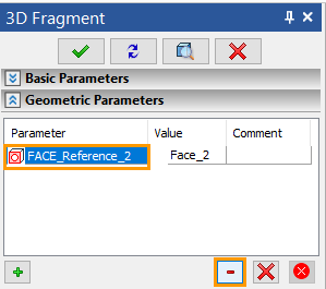
If you have problems updating the geometry of a fragment, you can remove the reference element from the geometry parameters.
To remove a reference element from the geometric parameters, open the fragment's context menu (via the 3D Model window or the Assembly Structure window) and select ![]() Edit. You should expand the Geometric Parameters tab in the parameters window of the fragment and delete the geometrical parameter by pressing
Edit. You should expand the Geometric Parameters tab in the parameters window of the fragment and delete the geometrical parameter by pressing ![]() icon.
icon.

Non-adaptive fragment with reference elements. This variant of the fragment is one of the most common. This fragment can be created in the following cases:
•the user creates a fragment in the context of an assembly for which the fragment is a second-level fragment or lower;
•the user specifies the source geometry not in the assembly, but in the fragments;
•the user cancels the Create geometric adaptive parameters option when creating a reference element;
•the user selected the Create Fragment option in the Detail > Create command;
•the user removed reference elements from the geometric parameters of the fragment.