3D Weld |
  
|
Calling the command:
Icon |
Ribbon |
|---|---|
|
Assembly (3D) > Assembly > Weld > Weld Weld > Weld > 3D Weld |
Keyboard |
Textual Menu |
<W3> |
Tools > Weld > 3D Weld |
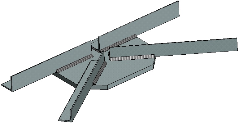
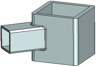
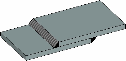
The weld modeling commands of T-FLEX CAD allow creating welds not only in a 2D drawing, but also within a 3D model. Welds appear in the 3D scene as special “cosmetic” bodies with a specific texture.

You can make an annotation for a 3D weld just like you do for a weld in a 2D drawing. The annotation can be created directly in the 3D model (it will be a 3D leader note), or on a 2D projection of such model.
When you create the table of welds on one of 2D pages of a given document, the 3D welds are entered in it along with the 2D welds.
Basic Information about 3D Welds
A 3D weld can be created by various means. All methods of creating 3D welds can be classified in groups:
•3D welds created on faces of the 3D model;
•3D welds created by guides: By Path and By 3 Paths;
•3D welds created on edges, 3D paths, 3D profiles, and operations;
•3D welds created by already existing 3D welds.
For 3D welds created by edges and by guides a new “cosmetic” body is created in the 3D scene. These welds do not influence the remaining part of the 3D model and are It is not entered in the 3D model history. In the 3D model tree, a 3D weld body is put into a separate Welds folder. If a 3D weld is created by other methods, the new body will not be created. The weld will be represented in the 3D scene by the model elements on which it is based.
By using various methods of creating 3D welds in T-FLEX CAD, you can simulate various types of welds in the 3D model.


For any 3D weld it is possible to specify to which weld type it belongs. The type determines all basic characteristics of the weld (type of weld joint, structural elements, annotation). The type of the weld does not depend on the way the weld was created.
The weld type is created as a separate model element. The weld types defined in the current document are common across both the 2D and 3D welds. A detailed description of weld types is available in the Weld Type section.
Specifying a weld type is not mandatory. If type is not specified, weld is called nonstandard. Nonstandard 3D welds can be used to decorate the 3D model. For example, suppose, the user wants to draw a weld on the model simply to make it look more realistic, without an intention to create weld documentation in the future. In such a case, it may not be justifiable to spend time on creating a weld type. You can simply define a nonstandard 3D weld in the 3D model.
Please distinguish between the “nonstandard” 3D weld and a 3D weld created by the nonstandard weld type, whose parameters were custom-defined by the user. The 3D weld of a nonstandard type is entered in the welds table.
Topic in this section: