2D Weld |
  
|
Calling the command:
Icon |
Ribbon |
|---|---|
|
Assembly (2D) > Assembly > Weld > Weld Weld > Weld > 2D Weld |
Keyboard |
Textual Menu |
<WE> |
Tools > Weld > 2D Weld |
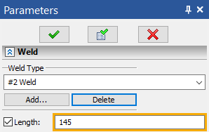
To create a welded seam, after invoking this command it is required to select the welded seam type in the Weld section of the properties window. In the drop down list those types of welded seams which were defined in the given document will be present.
If the required welded seam type is not yet created, it is possible to use the Add button. When pressing this button, the command of creation of the new welded seam type will be started. After completion of the type creation the system will return to the command of welded seam creation. Created seam type will automatically be selected.
If not a single welded seam type is defined in the current document at the moment of launching the Weld command, the command of welded seam type creation will automatically be invoked.
After selection of the type, it is possible to complete the seam creation. 2D welded seam not associated with the drawing’s elements will be created. Its length by default is equal to zero. If necessary, the length of the welded seam can be specified manually. To do so, it is required to enable the Length flag and specify the desired length of the welded seam in the input field that appears to the right.

To link the welded seam being created with the lines of a 2D drawing, it is required to indicate the graphic lines or 2D paths in 2D window with the help of the options of automenu:
|
<I> |
Select graphic lines |
|
<P> |
Select paths |

By default, both of these options are enabled.
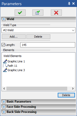
The elements selected in 2D window are added to the Elements list. To refuse selection of any element, it is required to select it in the list with the help of ![]() and press the Delete button.
and press the Delete button.
By default the length of welded seam associated with the drawing’s elements is determined automatically based on the length of selected lines or paths. If necessary, the length can also be specified manually by enabling the flag Length.
Basic Parameters and Sides Processing
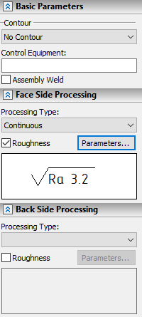
Parameters set in Basic Parameters, Face Side Processing and Back Side Processing sections are used for creation of weld symbols.

In the Basic Parameters section the following parameters can be specified:
•Contour:|
oNo Contour
oOpen Contour
When using this option, the symbol of open contour is displayed in the end of the text of weld symbol's shoulder

oWeld all around
When using this option, the symbol of closed contour is displayed at the joint of arrow line and shoulder of weld symbol.

•Assembly Weld
If this checkbox is enabled, then the symbol of assembly weld is displayed at the joint of arrow line and shoulder of weld symbol.

•Control Equipment
The text specified in this box will be displayed below the arrow line of weld symbol.
In the Face Side Processing and Back Side Processing sections, the ways of processing the front and back sides of the welded seam are specified. Face side processing parameters are displayed above the shoulder of weld symbol, back side processing - below.
The Processing Type parameter found in each of these sections allows us to select one of the following types of processing for each side of the welded seam:
•No Processing
•Face Reinforcement

•Continuous

To specify roughness of the front or back sides of the welded seam after machining, the Roughness flag in the corresponding section of the properties window should be enabled. As a result the Parameters button will become available to the right of the given flag. When pressing this button, the roughness’s parameters dialog will open. After specifying the desired parameters and closing the dialog, the image of the given roughness symbol will appear in the preview field located below. The specified roughness symbol is added to the end of the text of weld symbol's shoulder