Weld Symbol |
  
|
Calling the command:
Icon |
Ribbon |
|---|---|
|
Assembly > Assembly > Weld > Weld Symbol Title Block > Weld Table > Weld Symbol Weld > Weld > Weld Symbol |
Keyboard |
Textual Menu |
<WN> |
Title Block > Weld Table > Weld Symbol Tools > Weld > Weld Symbol |
The command is used for annotating weld seams in drawing and 3D scene.
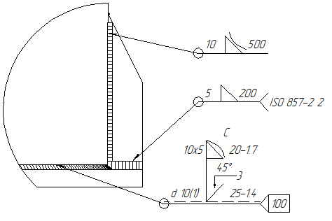
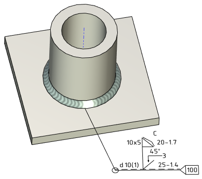
The ![]() Weld Symbol command based on the
Weld Symbol command based on the ![]() Leader Note command and share with it the common arrows and shoulders creation mechanics, common parameters and automenu options. This section describes only the specific parameters and options of weld symbols, which distinguish them from casual leader notes. The info on shoulders (except special welding shoulders) can be found in such sections as Main Shoulder of Leader Note and Additional Shoulders of Leader Note. The info on arrows creation mechanics and parameters can be found in such sections as: Shape and Position of Leader Note's Arrow, Additional Arrows of Leader Note, Parameters of Leader Note's Arrows. The info on font parameters can be found in the Font Parameters of Drawing Detailing Elements section.
Leader Note command and share with it the common arrows and shoulders creation mechanics, common parameters and automenu options. This section describes only the specific parameters and options of weld symbols, which distinguish them from casual leader notes. The info on shoulders (except special welding shoulders) can be found in such sections as Main Shoulder of Leader Note and Additional Shoulders of Leader Note. The info on arrows creation mechanics and parameters can be found in such sections as: Shape and Position of Leader Note's Arrow, Additional Arrows of Leader Note, Parameters of Leader Note's Arrows. The info on font parameters can be found in the Font Parameters of Drawing Detailing Elements section.
In addition to common leader note creation options, the automenu of the ![]() Weld Symbol command contains the additional option, that allows you to select a weld seam:
Weld Symbol command contains the additional option, that allows you to select a weld seam:
|
<R> |
Select Weld |
To select a weld, move the cursor to lines or 2D paths of the drawing, with which the weld is connected, or to a 3D weld in 3D scene. When the weld is highlighted, you can select it by clicking ![]() . If the type is defined in the parameters of the selected weld, then designation of the selected weld will appear on the dynamic preview of the weld symbol linked to the cursor. Next, the symbol is attached to the drawing or 3D scene in the same way as a regular Leader Note.
. If the type is defined in the parameters of the selected weld, then designation of the selected weld will appear on the dynamic preview of the weld symbol linked to the cursor. Next, the symbol is attached to the drawing or 3D scene in the same way as a regular Leader Note.
This way in a drawing you can only select the projection lines of 3D welds. 2D welds can only be selected in the Welds window.
Parameters of the weld symbol can be set in the parameters window. The window is split into tabs. Such tabs as the Coordinates, Leader, Multiple Jogs, Arrows, Arrow, Arrow Text and Symbol on Arrow contain the same parameters as in the ![]() Leader Note command. The Additional tab is described separately and contains the parameters available only in the
Leader Note command. The Additional tab is described separately and contains the parameters available only in the ![]() Weld Symbol command.
Weld Symbol command.
For ISO and ANSI standards, type and content of the weld symbol's shoulder should be set manually. To do this, select a special shoulder type (![]() ANSI or
ANSI or ![]() ISO) in the Corner drop-down list of the Leader tab in the parameters window.
ISO) in the Corner drop-down list of the Leader tab in the parameters window.
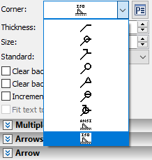
Such shoulders are special 2D fragments, whose parameters are set in the external variables dialog. This dialog can be called by clicking the ![]() icon located in the parameters window to the right of the Corner drop-down list. The button only appears upon selecting the corresponding shoulder type. The content of the dialog is different for different shoulder types (standards).
icon located in the parameters window to the right of the Corner drop-down list. The button only appears upon selecting the corresponding shoulder type. The content of the dialog is different for different shoulder types (standards).
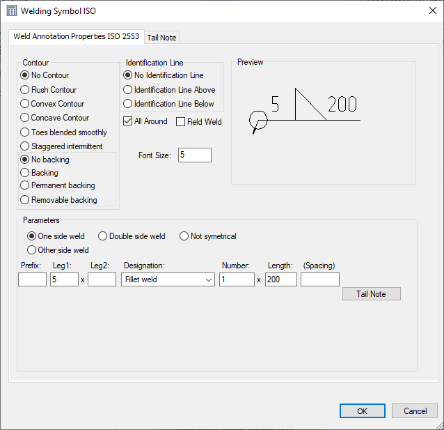
After confirming the entered values and specifying all the necessary parameters for the weld, a weld symbol will be created in the drawing.
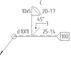
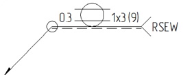
Additionally, T-FLEX CAD allows the user to create custom shoulder types for weld symbols. Custom shoulder types should be created as regular parametric fragments. Upon saving them into the "...\T-FLEX Parametric CAD xx\Libraries\System\Welding Symbols" folder, custom shoulder types appear in the Corner drop-down list.
Topics in this section: