Main Shoulder of Leader Note |
  
|
A position of leader note's main shoulder is defined by a position of a main arrow's ending point (see Shape and Position of Leader Note's Arrow). By default, a shoulder is created horizontally to the right side from ending point. You can sequentially rotate shoulder by 90 degree around arrow's ending point using the following automenu option:
|
<Z> |
Change leader line jog orientation |
Thus, the four variants of shoulder orientation are possible:

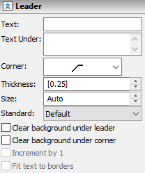
The Leader tab of the command's parameters window allows to define following parameters of the main shoulder:
Text
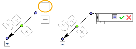
This is the text on the leader note's shoulder.
When defining this and other text parameters of a leader note, you can use variables by entering them in curly brackets (braces).
The text may also be defined using manipulator:
Text Under
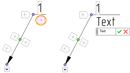
This is the text under all shoulders. It may also be defined using manipulator:
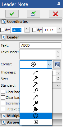
Corner
Defines the type of the shoulder. There are standard and custom types of shoulders

Thickness
Defines the thickness shoulder's lines. If the parameter value is shown in square brackets, then it is defined by Document Parameters (Document Parameters > Page > Lines > Lines > Other Lines).
Size
It defines the length of the shoulder. If the Auto value is used, it will automatically adjust to the length of the text.
Standard
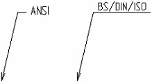
Defines the leader style standard. There are two standards for leaders - ANSI or BS/DIN/ISO. If this parameter is set to Default, then leader notes will follow the standard specified in Document Parameters (Document Parameters > Page > Detailing elements > Leader Notes > Standard)
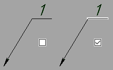
Clear background under leader
When this checkbox is enabled, the drawing elements behind the shoulder are not displayed.
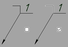
Clear background under corner
When this checkbox is enabled, the drawing elements behind the corner are not displayed.
Increment by 1
This parameter is only available until you initially place the ending point of a main arrow. It serves to quickly define BoM items. A number should appear on the shoulder instead of text – a BoM item position number. When the next leader note is created, the former current number is automatically incremented by one. It should be noted that, when using this approach, the number that appears on the leader will not be actually linked to the BoM position number.
If you want to establish a link between position number and leader note's text, so that it will update accordingly upon further changes, please refer to the Linking Leader Note to Product Composition section.
The special Callouts command is available for creating balloons on assembly drawing.
Fit text to borders
This checkbox can be enabled for circular shoulders ![]() (balloons). When it is disabled (by default), the balloon automatically stretches to fit a long text. When it is enabled, the balloon's size always remains default, and a font of a long text gets automatically narrowed in order to fit the balloon.
(balloons). When it is disabled (by default), the balloon automatically stretches to fit a long text. When it is enabled, the balloon's size always remains default, and a font of a long text gets automatically narrowed in order to fit the balloon.
Custom Leader Note's Shoulders
T-FLEX CAD allows a user to make his own types of leader note's shoulders. Custom shoulders are created as standard parametric fragments and saved in the folder …\T-FLEX Parametric CAD 17\Libraries\System\Leader Symbols (Leader Symbols library).
Files located in this folder are added as icons to the Corner list in the leader note command's parameters window and in leader note's parameters dialogs. Upon creating the leader note, location of the fragment-leader image is determined by the fixing vector which must exist in the fragment model.
For controlling parameters of the custom leader note, the dialog of the fragment variables or the custom dialog (if it was created in the fragment) will be used. To call the dialog of the fragment variables (or the custom dialog), use the special button ![]() which appears in leader note's parameters or call the Annotation Properties… command in the contextual menu of a leader note that uses a custom shoulder.
which appears in leader note's parameters or call the Annotation Properties… command in the contextual menu of a leader note that uses a custom shoulder.
See also:
•Linking Leader Note to Product Composition