Leader Note |
  
|
The command for creating leader notes can be called in one of the following ways:
Icon |
Ribbon |
|---|---|
|
3D Model > Additional > Leader Note Draw > Appearance > Leader Note Assembly > Additional > Leader Note Sheet Metal (2D)> Appearance > Leader Note Sheet Metal (3D) > Additional > Leader Note Surfaces > Additional > Leader Note Weld > Additional > Leader Note Routing > Additional > Leader Note Primitives > Additional > Leader Note Remarks > Remarks > Leader Note Workplane > Appearance > Leader Note |
Keyboard |
Textual Menu |
<IN> |
Draw > Leader Note |
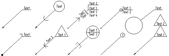
Leader notes are used for creating various drawing elements like BoM positions balloons, designations of brand marks, part codes, etc. Also, leader notes can be created in 3D window either on active workplane, or not. Usually, a leader note is composed of two parts: the arrow (leader) and the shoulder (note). If necessary, it is possible to create leader notes that contain several arrows. Arrows might be straight or have jogs.

When creating a leader note in 2D window or in the draw on workplane mode, following steps are performed upon calling the Leader Note command:
1.Setting the necessary configuration of options, which define the way of command's operation;
2.Defining a shape and position of a main arrow;
3.Defining an orientation, text and other parameters of a main shoulder;
4.Adding additional shoulders and defining their parameters;
5.Adding additional arrows;
6.Defining parameters of each arrow;
7.Defining font parameters;
8.Finishing input ![]() .
.
The only mandatory steps are defining a starting node and an ending node of a main arrow. If the Create Automatically option is disabled, then finishing input is also mandatory. Other steps are optional.
When defining positions of arrow's nodes, command's automenu contains specific set of options described in the Shape and Position of Leader Note's Arrow section plus following options, which are common for most 2D elements creation commands:
|
<Ctrl>+<Enter> |
Finish input |
|
<P> |
|
|
<Alt>+<P> |
|
|
<Esc> |
Exit command |
Copying parameters of a leader note doesn't copy its text.
After defining a position of main arrow's ending node the leader note' creation command essentially switches to the editing mode, which have the same set of automenu options as the leader note's editing command has upon selecting a single leader note. During editing of arrow's nodes and adding additional nodes using manipulators both sets of options are available simultaneously.
Creating a leader note in 3D scene without drawing on a workplane has some specifics, but for the most part is similar to the way of operation described above.
Special commands are available for creating assembly drawing's balloons, bend notes and weld symbols.
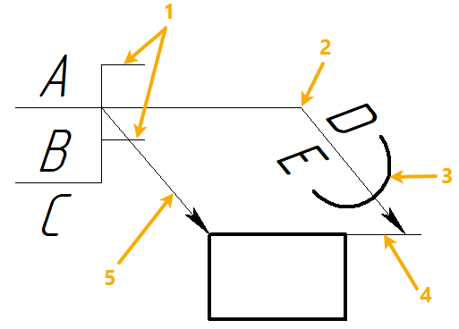
Main Components of Leader Note

A - text of the main shoulder
B - text of the additional shoulder
C - text below shoulders
D - text above the main arrow
E - text below the main arrow
1 - corners of shoulders
2 - jog of the main arrow
3 - symbol on the main arrow
4 - witness line of the main arrow
5 - additional arrow
Automatic Finishing of Leader Note’s Creation
By default, after defining positions of main arrow's starting and ending points the command remains in the mode of editing the created leader note. This allows us to add to the leader note the necessary number of additional arrows, create jogs on the arrows, specify and edit leader note’s parameters. After finalizing the leader note's appearance, it is required to explicitly confirm its creation by clicking the ![]() button in the command’s parameters window or pressing <Enter>.
button in the command’s parameters window or pressing <Enter>.
It is also possible to use another work algorithm. In the Options tab of the command’s parameters window you can find the Create automatically checkbox. When this checkbox is enabled, creation of the leader note will automatically be completed right after positioning the ending point of the main arrow (which also defines the position of the main shoulder).
Note that in this case it is required either to specify parameters of the leader note being created before positioning of the ending node or additionally enable the Show parameters dialog for each element checkbox. In the latter case, after positioning the ending point, the leader note’s parameters dialog will appear on the screen. This allows us to work as with the previous versions of T-FLEX CAD – first specify location of an element on the drawing and then specify its parameters.

Commands for Creating Assembly Drawing's Balloons, Bend Notes and Weld Symbols.
You can use the basic Leader Note command for creating assembly drawing's balloons (see Linking Leader Note to Product Composition), bend notes, weld symbols and leader notes referring to drawing notes if necessary. However, it is more convenient to use special command, which provide extended capabilities:
•![]() Callouts
Callouts
These commands use the basic Leader Note command for actual creation of designations, so they have similar basic principles and user interface, but additionally provide the ability to create multiple notes at once, automatic detection of bend lines and weld type, creating associative links between drawing notes' records and leader note, as well as compliance with specific standards.
Default parameters of basic leader notes, assembly drawing's balloons, bend notes and weld symbols are handled independently of each other.
Topics in this section:
•Shape and Position of Leader Note's Arrow
•Linking Leader Note to Product Composition
•Additional Shoulders of Leader Note
•Additional Arrows of Leader Note
•Parameters of Leader Note's Arrows
•Options of Creating Leader Notes
•Parameters Dialog of Leader Note
See Also:
•Snapping Dimensions and Leader Notes to Drawing Views
•Font Parameters of Drawing Detailing Elements
•Change Size of Font and Arrows for All Elements on Current Page