Shape and Position of Leader Note's Arrow |
  
|
In addition to the ![]() Leader Note, the information in this section is also applicable to the
Leader Note, the information in this section is also applicable to the ![]() GD&T Formlimits and
GD&T Formlimits and ![]() Datum commands.
Datum commands.
Upon calling the Leader Note command, it is mandatory to define positions of two nodes (starting and ending) of the main arrow. Position of the ending node also defines a position of the main shoulder of the leader note. For GD&T symbols, the ending node of the main arrow is the anchor point of the frame.
Along with starting and ending nodes, arrow may have transitional nodes defining jogs.
When creating a leader note on a drawing or in the draw on workplane mode, nodes' positions might be either free or linked to some existing elements. A created link might be deleted if necessary.
When creating a leader node in the 3D view window without drawing on a workplane, the starting node of the arrow should always be linked to some element of a model. Such linking can not be deleted. See more in Leader Note in 3D Scene.
Free Positioning of Leader Note's Arrow Nodes
At first, the manipulator ![]() of arrow's starting node and the preview of the leader note are attached to the cursor. Absolute coordinates of the node are displayed in the Coordinates tab of command's parameters window. They are dynamically tracked as the cursor moves in the drawing window.
of arrow's starting node and the preview of the leader note are attached to the cursor. Absolute coordinates of the node are displayed in the Coordinates tab of command's parameters window. They are dynamically tracked as the cursor moves in the drawing window.
![]()
Enabling a checkbox located near the X or Y coordinate's name fixes such coordinate, so it stops depend on cursor's position. Checkboxes are enabled automatically, when you type in coordinates using keyboard. Fixing of coordinates is indicated by a dashed blue line on a drawing: vertical for X coordinate, horizontal for Y.
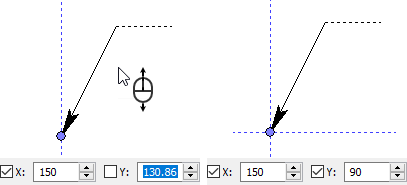
•Using the cursor
Simply place the cursor in the necessary position and click ![]() .
.
•Using the keyboard
Type in the X coordinate, then either press <Tab> or click ![]() the Y coordinate's input box, then type in the Y coordinate and click
the Y coordinate's input box, then type in the Y coordinate and click ![]() at any position within the 2D or 3D window (depending on which window you're working in).
at any position within the 2D or 3D window (depending on which window you're working in).
•Using the combination of aforementioned methods
Type in one of the coordinates first, then define the second one using the cursor.
After positioning the starting node, its manipulator disappears and the manipulator ![]() of the ending node gets attached to the cursor. By default, the ending node is positioned in relation to the starting one. Therefore, the relative coordinates dx and dy are used instead of absolute X and Y.
of the ending node gets attached to the cursor. By default, the ending node is positioned in relation to the starting one. Therefore, the relative coordinates dx and dy are used instead of absolute X and Y.
![]()
For positioning the ending node in absolute coordinates you need to disable the following automenu option:
|
<F> |
Attach to Arrow |
If the ending node is positioned in relative coordinates, then the ending node follows the starting one, when editing the starting node's position. If the ending node is positioned in absolute coordinates, then editing the starting node's position doesn't affect the ending node.
|
||
Initial shape of the leader note |
The result of repositioning the starting node |
|
Attaching to arrow is disabled |
Attaching to arrow is enabled |
|
Regardless of the type of used coordinates, they're inputted in the same way as described above.
After positioning the ending node, the arrow configuration no longer depends on the cursor movement and all manipulators of arrow's nodes are displayed as well as the main shoulder's text input box ![]() (see Main Shoulder of Leader Note). If you cancel
(see Main Shoulder of Leader Note). If you cancel ![]() the text input, then manipulators
the text input, then manipulators ![]() for adding text of the main shoulder and below shoulders also appear.
for adding text of the main shoulder and below shoulders also appear.
Note that, after positioning the ending node of the arrow, the input focus is automatically shifted to the main shoulder's text input box. If you confirm the text input using <Enter> or ![]() , it will finish the leader note's creation.
, it will finish the leader note's creation.

Usage of manipulators for changing the appearance and and size of arrow's starting node ![]() , adding a symbol on arrow
, adding a symbol on arrow ![]() , adding text above and below arrow
, adding text above and below arrow ![]() , is described in the Parameters of Leader Note's Arrows section.
, is described in the Parameters of Leader Note's Arrows section.
The green circle manipulator ![]() allows adding an transitional node to the arrow. Positioning of transitional nodes is performed in the same way as positioning of the ending node either in absolute or relative coordinates. After adding a transitional node, new manipulators
allows adding an transitional node to the arrow. Positioning of transitional nodes is performed in the same way as positioning of the ending node either in absolute or relative coordinates. After adding a transitional node, new manipulators ![]() for adding more transitional nodes appear on each segment of the arrow. Thus, you can can create arrows with multiple jogs
for adding more transitional nodes appear on each segment of the arrow. Thus, you can can create arrows with multiple jogs
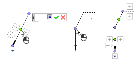
Each node of the created arrow can be repositioned. To do so, click ![]() the manipulator
the manipulator ![]() of a necessary node. The node will start following the cursor, so you can input its coordinates in the same way as they were initially defined.
of a necessary node. The node will start following the cursor, so you can input its coordinates in the same way as they were initially defined.
If you want to delete a transitional node, click ![]() its manipulator
its manipulator ![]() and then use the following automenu option:
and then use the following automenu option:
|
<Del> |
Delete point |
Linking Leader Note's Arrow Nodes to Drawing’s Elements
Any of arrow's nodes can be linked:
•to 2D node or intersection/connection point of construction or graphic lines (selecting an intersection point automatically creates a 2D node, selecting a connection point links the arrow to endpoint of one of the connected lines);
•to construction or graphic line;
Linking Leader Note's Arrow Nodes to 2D Nodes
When positioning an arrow's node, activate the following automenu option in order to link it to a 2D node:
|
<N> |
Select Node |
Then move the cursor over a necessary 2D node and click![]() .
.
First node of an arrow can be link without activating this option. Simply move the cursor over a 2D node (with active 2D nodes snapping filter on the filter toolbar) and click ![]() - link will be created anyway. However, when positioning other nodes of an arrow, activating the option is mandatory for establishing a link.
- link will be created anyway. However, when positioning other nodes of an arrow, activating the option is mandatory for establishing a link.
If you activate the option and click ![]() a blank area of a drawing without pointing directly to the 2D node, the system will detect a nearest existing 2D node automatically.
a blank area of a drawing without pointing directly to the 2D node, the system will detect a nearest existing 2D node automatically.
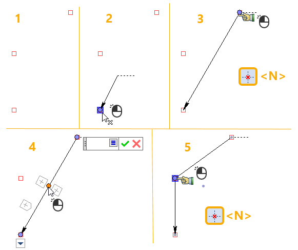
In result, arrow's node coordinates will always coincide with the selected 2D node's coordinates, upon further changes in the latter. Additionally you can apply an offset from the selected 2D node. To do so, return to editing arrow's node by clicking its manipulator ![]() . The arrow's node starts following the cursor. Link between the arrow's node and the 2D node is indicated by the dashed line. The Coordinates tab of the command's parameters window contains offsets dx and dy from the linked 2D node. Then you can input required offsets in one of the ways described above.
. The arrow's node starts following the cursor. Link between the arrow's node and the 2D node is indicated by the dashed line. The Coordinates tab of the command's parameters window contains offsets dx and dy from the linked 2D node. Then you can input required offsets in one of the ways described above.
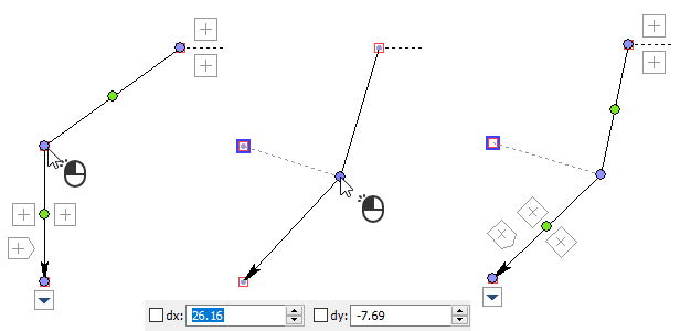
Use the following automenu option for deleting offsets and snapping the arrow's node directly to the 2D node again:
|
<F> |
Link to Node |
Linking Leader Note's Arrow Nodes to Construction and Graphic Lines
Linking to a construction line is only possible, if at least one 2D node lays on such line.
Move the cursor over a construction or graphic line, when positioning an arrow's node, in order to link it. The line gets highlighted in red (graphic) or green (construction). Then click ![]() the line. In result, the arrow's node starts moving along the selected line as you move the cursor. Place the node in necessary position and click
the line. In result, the arrow's node starts moving along the selected line as you move the cursor. Place the node in necessary position and click ![]() to finish positioning.
to finish positioning.
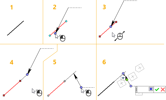
As you move the node along the selected line, the Coordinates tab of the command's parameters window contains the Offset parameter, which defines the position of the node on the selected line.
The offset on curves (circle, arc ellipse, spline) is measured in relative units ranging from 0 to 1, where 0 - start of the curve, 1 - end of the curve. Start and end of closed curve are the same point.
The offset for straight lines is measured in absolute units from the starting or ending point of the line, depending on which point is closer to the current position of the node.
If a starting node of an arrow is linked to a straight line, but lays beyond its limits, then a witness line is drawn between the line and the node. Witness line can be disabled by disabling the Draw Leader checkbox in arrow parameters.
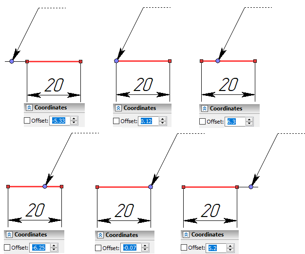
You can type in the offset value using the keyboard for precise positioning. Typing in the value enables the checkbox located to the left side of the Offset input box. In result, the node stops following the cursor. Dashed blue lines indicate fixing of the offset. Click ![]() anywhere on the drawing to confirm the positioning.
anywhere on the drawing to confirm the positioning.
Alternatively, you can use the following automenu option:
|
<L> |
Set relation with Line |
Click ![]() anywhere on the drawing after activating the option, and the system will automatically detect the nearest construction line.
anywhere on the drawing after activating the option, and the system will automatically detect the nearest construction line.
Linking to a construction line is only possible, if at least one 2D node lays on such line.
This option isn't mandatory for establishing a link, unlike the similar option for linking to a 2D node.
The leader note has following modes of handling the angle between the arrow and first node's linking line:
|
<U> |
Fixing to Point |
|
<U> |
Angle Fixing |
|
<U> |
Orthogonal Fixing |
Sequentially click the corresponding automenu option or press <U> to switch between modes.
Fixing to point ![]() preserves the position of the second node of the arrow in relation to the first node upon further repositioning of the first node.
preserves the position of the second node of the arrow in relation to the first node upon further repositioning of the first node.
Angle Fixing ![]() preserves the angle between the arrow and the linking line upon further repositioning of the first node.
preserves the angle between the arrow and the linking line upon further repositioning of the first node.
Orthogonal Fixing ![]() keeps the arrow normal to the linking line upon further repositioning of the first or second node.
keeps the arrow normal to the linking line upon further repositioning of the first or second node.
Regardless of which node is being currently edited, these modes are applied to the angle of the arrow's starting segment, i.e. the segment between the first and second node. Second node might be ending or transitional.
Switching modes has no effect if first node has no linking, first or second node is linked to a 2D node, or second node is linked to a line.
|
|
Initial configuration |
Results of repositioning starting nodes |
Linking of an arrow's node to a 2D node, construction line or graphic line can be canceled using the following automenu option:
|
<K> |
Break relations |
See Also: