GD&T Feature Control Frame |
  
|
The GD&T Formlimits command can be called in one of the following ways:
Icon |
Ribbon |
|---|---|
|
3D Model > Additional > GD&T Formlimits Draw > Appearance > GD&T Formlimits Assembly > Additional > GD&T Formlimits Sheet Metal (2D) > Appearance > GD&T Formlimits Sheet Metal (3D) > Additional > GD&T Formlimits Surfaces > Additional > GD&T Formlimits Weld > Additional > GD&T Formlimits Routing > Additional > GD&T Formlimits Primitives > Additional > GD&T Formlimits Remarks > Remarks > GD&T Formlimits Workplane > Appearance > GD&T Formlimits |
Keyboard |
Textual Menu |
<FO> |
Draw > GD&T Formlimits |
The command creates geometric dimensioning and tolerancing feature control frames.
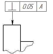
The ![]() GD&T Formlimits command is closely related to the
GD&T Formlimits command is closely related to the ![]() Datum command. In order to switch from creating a feature control frame to creating a datum use the following automenu option:
Datum command. In order to switch from creating a feature control frame to creating a datum use the following automenu option:
|
<O> |
Create leader or datum with leader |
You can switch between the ![]() GD&T Formlimits and
GD&T Formlimits and ![]() Datum at any stage of working with the corresponding command. Both commands are based on the
Datum at any stage of working with the corresponding command. Both commands are based on the ![]() Leader Note command and share with it common mechanics of arrows creation and parameters. This section describes the specific parameters of the
Leader Note command and share with it common mechanics of arrows creation and parameters. This section describes the specific parameters of the ![]() Datum command, which distinguish it from other mentioned commands. The common info on creating and editing datum feature symbols and feature control frames can be found in the GD&T Symbols section. Info on arrows can be found in such sections as: Shape and Position of Leader Note's Arrow, Additional Arrows of Leader Note, Parameters of Leader Note's Arrows. The info on font parameters can be found in the Font Parameters of Drawing Detailing Elements section.
Datum command, which distinguish it from other mentioned commands. The common info on creating and editing datum feature symbols and feature control frames can be found in the GD&T Symbols section. Info on arrows can be found in such sections as: Shape and Position of Leader Note's Arrow, Additional Arrows of Leader Note, Parameters of Leader Note's Arrows. The info on font parameters can be found in the Font Parameters of Drawing Detailing Elements section.
Compound frames
A feature control frame without arrows can be snapped to another feature control frame already existing on the drawing using the following automenu option:
|
<T> |
Select GD&T Formlimits Symbol |
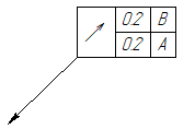
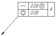
Upon activating this option, you should select an existing feature control frame via ![]() . The newly created feature control frame will be positioned below the selected one. If both frames contain the same type of tolerance or refer to the same datum, then the tolerance type cells or datum cells of both frames are merged. Thus you can create compound frames consisting of any number of frames.
. The newly created feature control frame will be positioned below the selected one. If both frames contain the same type of tolerance or refer to the same datum, then the tolerance type cells or datum cells of both frames are merged. Thus you can create compound frames consisting of any number of frames.
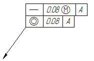
Moreover, you can snap a new feature control frame to a characteristic point of another frame ![]() using object snapping without activating the aforementioned option. In this case, cells are not merged.
using object snapping without activating the aforementioned option. In this case, cells are not merged.
Feature control frame parameters
At any moment of feature control frame creation it is possible to specify the frame’s parameters in the command’s parameters window. To make the work more convenient, the window is split into several tabs. Some of the tabs, such as Coordinates, Arrows, Arrow, Arrow Text, Symbol on Arrow, are the same as in the ![]() Leader Note command. The Options tab is common for the
Leader Note command. The Options tab is common for the ![]() Datum and
Datum and ![]() GD&T Formlimits commands. The Tolerance, Base and Placement tabs are described below.
GD&T Formlimits commands. The Tolerance, Base and Placement tabs are described below.
The tab contains following parameters:
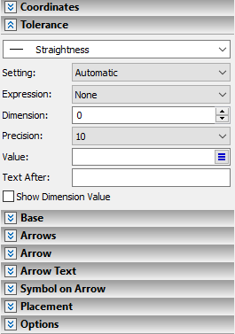
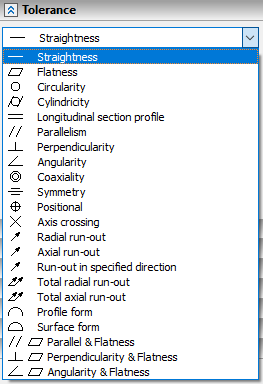
Type of tolerance
You can select a type of tolerance in the drop-down list located at the top of the tab. The symbol of the selected type is displayed in the drawing in the first cell of the feature control frame.
Setting
This parameter defines, whether the tolerance value should be inputted manually, or calculated automatically depending on the dimension value and precision.
Expression
This drop-down list contains a symbol to be displayed in the second cell of the frame in front of the tolerance value. Following symbols are available:
Name |
Symbol in a drawing |
Applicability by GOST |
None |
|
|
R |
R |
To be used, if a circular or cylindrical tolerance zone |
D |
Ø |
To be used, if a circular or cylindrical tolerance zone |
Sphere R |
Sphere R |
To be used, if a spherical tolerance zone |
Sphere D |
Sphere Ø |
To be used, if a spherical tolerance zone |
T |
T |
To be used, if Symmetry, Axis crossing, Profile any line, Profile any surface, Position (in the case when range of Position tolerance is bound by two parallel lines or planes) tolerance is defined by a diameter |
T/2 |
T/2 |
To be used, for same types of tolerance, as the the previous symbol, if a tolerance zone |
Dimension
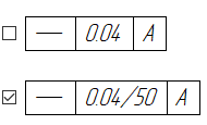
Nominal value of the dimension, upon which the value of the tolerance depends on. If a tolerance is linked to a dimension, then this box is non-editable and contains the nominal value of the linked dimension The value of the dimension affects the tolerance’s value in automatic calculation. By default, a dimension value itself is not displayed in feature control frame. If you enable the Show Dimension value checkbox located at the bottom of the tab, then the dimension value will be displayed in the feature control frame, right after the tolerance value, separated by the "/".
Precision
Tolerance precision grade in accordance with GOST 24643-81.Takes integer values in the range from 3 to 16, inclusive. This parameter is applied, only when using the automatic tolerance value calculation.
Value
The value of the tolerance, either input manually or calculated automatically. When inputting value manually you can use the predefined ![]() list of values.
list of values.
Text After
A text string to be displayed at the end of the second cell of frame after tolerance and dimension values. You can input an arbitrary text via keyboard or use contextual menu commands.
Show Dimension Value
By default, this checkbox is disabled, so the dimension value set in feature control frame parameters is not displayed in the frame itself. If you enable the checkbox, then the dimension value will be displayed in the feature control frame, right after the tolerance value, separated by the "/".
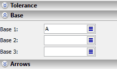
The tab contains names of datums (bases), which the specified tolerance refers to. Names of datums are the capital letters to be displayed in the third, fourth and fifth cells of the feature control frame. You can input a name via keyboard, use contextual menu commands, or insert a letter from the ![]() list. Unlike the Datum command, the automatic base naming is not available for feature control frames.
list. Unlike the Datum command, the automatic base naming is not available for feature control frames.
Keep in mind, that names of datums in feature control frames are NOT updated automatically, upon changing names in datum feature symbols.
The tab contains following parameters:
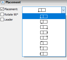
Placement
The position of the frame in relation to its anchor point. Eight different positioning options are available in the drop-down list.
When creating a frame with arrows, the ending node of the main arrow is the anchor point of the frame. This checkbox is disabled by default, which results in automatic positioning of the anchor point in relation to the frame, depending on the direction, where the arrow comes from. If you enable the checkbox, then the positioning option selected in the drop-down list will always be applied, regardless of the direction, where the arrow comes from, which may result in arrow overlapping the frame.
When creating a frame without arrows, enabling/disabling this checkbox only affects the ability to switch the positioning option via the drop-down list, while the selected option is always applied, regardless of the state of the checkbox.
Rotate 90°
By default, this checkbox is disabled, so the feature control frame is horizontal and the cells are ordered left to right. If you enable the checkbox, then the frame will be vertical and the cells will be ordered bottom to top.
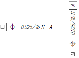
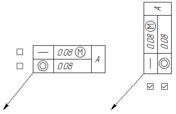
For each frame merged into the compound one the checkbox should be handled individually.
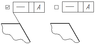
Leader
This checkbox is applicable and active only for frames without arrows. It controls the drawing of the witness line between the linked node/line and the frame.
See Also:
•Linking GD&T Symbols to Dimensions
•Parameters Dialog of GD&T Symbols
•Shape and Position of Leader Note's Arrow
•Additional Arrows of Leader Note
•Parameters of Leader Note's Arrows
•Font Parameters of Drawing Detailing Elements
•Change Size of Font and Arrows for All Elements on Current Page