GD&T Symbols |
  
|
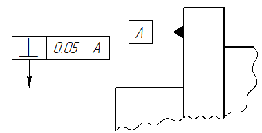
GD&T symbols are feature control frames and datum feature symbols.

Feature control frames are created using the ![]() GD&T Formlimits command. Datum feature symbols are created using the
GD&T Formlimits command. Datum feature symbols are created using the ![]() Datum command. Both commands are closely related to each other. Upon calling one of them, you can quickly switch to another using the following automenu options:
Datum command. Both commands are closely related to each other. Upon calling one of them, you can quickly switch to another using the following automenu options:
|
<O> |
Create leader or GD&T Formlimits with leader |
|
<O> |
Create leader or datum with leader |
Both commands are based on the ![]() Leader Note command and share with it the common arrows creation mechanics and parameters. The difference is, that the special standard frames containing the GD&T information are used instead of the leader note shoulders. This section contains common info on creating and editing GD&T symbols. The info on specific parameters of particular types of GD&T symbols can be found in GD&T Feature Control Frame and GD&T Datum sections. The info on arrows creation mechanics and parameters can be found in such sections as: Shape and Position of Leader Note's Arrow, Additional Arrows of Leader Note, Parameters of Leader Note's Arrows. The info on font parameters can be found in the Font Parameters of Drawing Detailing Elements section.
Leader Note command and share with it the common arrows creation mechanics and parameters. The difference is, that the special standard frames containing the GD&T information are used instead of the leader note shoulders. This section contains common info on creating and editing GD&T symbols. The info on specific parameters of particular types of GD&T symbols can be found in GD&T Feature Control Frame and GD&T Datum sections. The info on arrows creation mechanics and parameters can be found in such sections as: Shape and Position of Leader Note's Arrow, Additional Arrows of Leader Note, Parameters of Leader Note's Arrows. The info on font parameters can be found in the Font Parameters of Drawing Detailing Elements section.
When creating a GD&T symbol in 2D window or in the drawing on workplane mode, following steps are performed upon calling the corresponding command:
1.Setting the necessary configuration of options, which define the way of command's operation;
2.Defining a shape and position of a main arrow;
3.Defining specific parameters of a feature control frame or a datum feature symbol;
4.Adding additional arrows;
5.Defining parameters of each arrow;
6.Defining font parameters (frame size depends on the font size):
7.Finishing input ![]() .
.
By default, GD&T symbols are created with an arrow. In this mode, the only mandatory steps are specifying a starting node and an ending node of a main arrow. The ending node will define the position of the frame.
Unlike leader notes, GD&T symbols can be created without arrow. To do so, you have to delete the arrow, using the following automenu option:
|
<Shift>+<D> |
Delete Arrow |
Upon deleting the arrow, you only have to specify a single node, which defines the frame position.
If the Create Automatically option is disabled, then finishing input is also mandatory. Other steps are optional.
When defining positions of arrow's nodes, command's automenu contains specific set of options described in the Shape and Position of Leader Note's Arrow and the Linking GD&T Symbols to Dimensions section plus following options, which are common for most 2D elements creation commands:
|
<Ctrl>+<Enter> |
Finish input |
|
<P> |
Set GD&T Formlimit Parameters |
|
<Alt>+<P> |
|
|
<F4> |
|
|
<Esc> |
Exit command |
After defining a position of main arrow's ending node the symbol's creation command essentially switches to the editing mode, which have the same set of automenu options as the GD&T symbols editing command has upon selecting a single symbol.
Creating a GD&T symbol in 3D scene without drawing on a workplane has some specifics, but for the most part is similar to the way of operation described above.
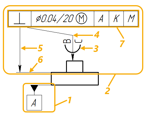
Main Components of GD&T Symbols

1 - datum feature symbol
2 - feature control frame, including:
3 - symbol on the additional arrow
В - text above the additional arrow
С - text below the additional arrow
4 - jog of the additional arrow
5 - main arrow
6 - witness line of the main arrow
7 - frame, including:
⊥ - type of tolerance (perpendicularity)
Ø - expression (diameter)
0.04 - tolerance value
20 - dimension value
Ⓜ - text after value (maximum material condition)
А, К, М - names of related datums
Automatic Finishing of Symbol’s Creation
By default, after defining positions of main arrow's starting and ending points the command remains in the mode of editing the created symbol. This allows us to add the necessary number of additional arrows, create jogs on the arrows, specify and edit symbol’s parameters. After finalizing the symbol's appearance, it is required to explicitly confirm its creation by clicking the ![]() button in the command’s parameters window or pressing <Enter>.
button in the command’s parameters window or pressing <Enter>.
It is also possible to use another work algorithm. In the Options tab of the command’s parameters window you can find the Create Automatically checkbox. When this checkbox is enabled, creation of the symbol will automatically be completed right after positioning the ending point of the main arrow (which also defines the position of the frame).
Note that in this case it is required either to specify parameters of the symbol being created before positioning the ending node, or additionally enable the Show Dialog for Each Element checkbox. In the latter case, after positioning the ending point, the symbol’s parameters dialog will appear on the screen. This allows us to work as with the previous versions of T-FLEX CAD – first specify location of an element on the drawing and then specify its parameters.

Topics in this section:
•Linking GD&T Symbols to Dimensions
•Parameters Dialog of GD&T Symbols
See Also:
•Shape and Position of Leader Note's Arrow
•Additional Arrows of Leader Note
•Parameters of Leader Note's Arrows
•Font Parameters of Drawing Detailing Elements
•Change Size of Font and Arrows for All Elements on Current Page