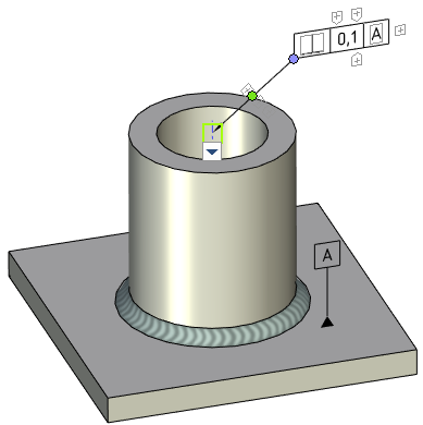
GD&T Symbols in 3D Scene |
  
|
Creating 3D GD&T symbols for the most part is the same as creating 2D ones. However, there are some specific requirement described below.
3D symbol can only have a single arrow. Adding additional arrows is not available.
A starting node of an arrow should be linked to some element of a model, so you have to select ![]() a node, face, edge or vertex in the 3D scene. Linking point on a face or edge is defined by a position of the cursor at the moment of selection.
a node, face, edge or vertex in the 3D scene. Linking point on a face or edge is defined by a position of the cursor at the moment of selection.
An ending node of an arrow can not be linked to a particular element. The user only sets the distance between nodes, while the plane of the symbol is selected arbitrarily by the system.
GD&T symbols in 3D have same manipulators as in 2D.

By default, parts of GD&T symbols as well as other 3D annotation elements hidden behind non-transparent elements of a 3D model are not displayed. If necessary, you can enable the Display annotations over 3D model option (Options > 3D > 3D).