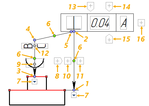
Manipulators of GD&T Symbols |
  
|
Manipulators can be used for quick editing of GD&T symbols. Manipulators are displayed, upon selecting a GD&T symbol in any view window, as well as upon moving the cursor over a symbol in 2D window or in drawing on active workplane mode. Click![]() on a manipulator to perform a corresponding action. The action will be performed within the GD&T symbols editing command which is automatically launched this way, even if the transparent editing of 2D elements is disabled.
on a manipulator to perform a corresponding action. The action will be performed within the GD&T symbols editing command which is automatically launched this way, even if the transparent editing of 2D elements is disabled.

1 |
- |
|
Change the position of the main arrow's starting node |
2 |
- |
|
Change the position of main arrow's ending node, |
3 |
- |
|
Change the position of the additional arrow's starting node |
4 |
- |
|
Change the position of the additional arrow's transitional node |
5 |
- |
|
Change the position of the additional arrow's ending node |
6 |
- |
|
Add a transitional node (jog) to an arrow |
7 |
- |
|
Change the appearance and size of arrow's starting node |
8 |
- |
|
Add a symbol on arrow |
9 |
- |
|
Change the position of the symbol on arrow |
10 |
- |
|
Add a text above the arrow' |
11 |
- |
|
Add a text below the arrow' |
12 |
- |
|
Change the position of texts above and below the arrow |
13 |
- |
|
Add an expression |
14 |
- |
|
Add a dimension value |
15 |
- |
|
Add a text after value |
16 |
- |
|
Add a datum |
The expression and text after manipulators are not available, until you set a tolerance value. If you set a dimension value, the tolerance value will be calculated automatically considering the specified precision. If necessary, you can change the precision or input a tolerance value manually. The dimension value is not displayed in the frame by default. In order to display it, you have to enable the Show Dimension Value checkbox in the parameters window.
Manipulators ![]()
![]()
![]() become orange
become orange ![]() upon hovering the cursor over them.
upon hovering the cursor over them.
Along with manipulators, the gray outline is displayed around the filled active cells, such as symbol on arrow, text above and below arrow, tolerance type, expression, tolerance and dimension values, text after value, datum names. Content of such cells can be edit either in the parameters window, or directly in the drawing window. In order to edit a cell content in the drawing window, click the cell with ![]() . Upon clicking an active cell, either the text input box
. Upon clicking an active cell, either the text input box ![]() (if the cell contains text), or symbol selection drop-down list (if the cell contains special symbols) appears nearby. You can confirm
(if the cell contains text), or symbol selection drop-down list (if the cell contains special symbols) appears nearby. You can confirm ![]() or cancel
or cancel ![]() text input using buttons located in right side of the input box.
text input using buttons located in right side of the input box.
Text input may also be confirmed using <Enter>, though it results in exiting the command with confirming changes. Input may also be canceled using the <Esc>. Pressing <Esc> exits the command, if the input focus is outside the aforementioned text input box.