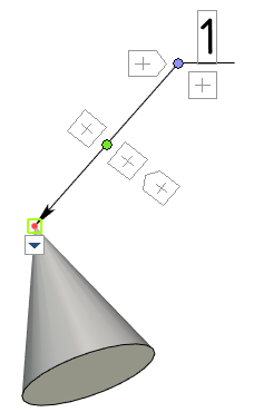
Leader Note in 3D Scene |
  
|
Creating 3D leader notes for the most part is the same as creating 2D leader notes. However, there are some specific requirement described below.
3D leader note can only have a single arrow. Adding additional arrows is not available.
A starting node of an arrow should be linked to some element of a model, so you have to select ![]() a node, face, edge or vertex in the 3D scene. Linking point on a face or edge is defined by a position of the cursor at the moment of selection.
a node, face, edge or vertex in the 3D scene. Linking point on a face or edge is defined by a position of the cursor at the moment of selection.
An ending node of an arrow can not be linked to a particular element, but it is always placed on a plane, which passes through a linking point of a starting node and is parallel to one the model's planes (to Front plane by default). Thus, a text of a leader note lays in the same plane. You can select another plane using the following automenu option:
|
<Т> |
Select Plane |
An angle between shoulder and arrow in the selected plane changes automatically depending on the camera position, ensuring the readability of a text.
Leader notes in 3D have same manipulators as in 2D.

By default, parts of leader notes as well as other 3D annotation elements hidden behind non-transparent elements of a 3D model are not displayed. If necessary, you can enable the Display annotations over 3D model option (Options > 3D > 3D).