Creating Libraries of Parametric Elements |
  
|
Creating Libraries of Parametric Elements |
|
T-FLEX CAD offers a rich library of standard elements included in the application installation package. The libraries of standard elements speed up the design process and allow the designer to concentrate on the actual development, rather than on drawing bolts and nuts alike.
Besides, T-FLEX system provides tools for the user to define one's own standard elements, that support wide range of productivity improvements. Designers often use families of elements whose members are mostly identical, often with the only difference in the dimension values, having to spend time just to draw such an element. This issue can be resolved by creating a standard parametric element in T-FLEX CAD system.
A big advantage of T-FLEX CAD compared to other systems is the provision for the user to create own standard parametric elements. This does not require knowledge of any programming language. The user can create any objects, from drawings and 3D models to dialog boxes for fragment insertion. T-FLEX CAD provides special commands for this purpose. Another positive feature is that any library element is an ordinary T-FLEX parametric drawing.
Creating parametric library elements
Parametric library element creation can be divided into several steps:
1. Creating databases (if necessary).
2. Creating variables, including those relying on databases.
3. Creating a parametric drawing and/or 3D model.
4. Creating fixing vectors and fixing LCS;
5. Creating 2D and/or 3D connectors;
6. Creating a dialog box of fragment’s parameters.
7. Adding the element to the library.
Some of these steps can be skipped. For example, you may not need a set of values from a database, or you're not creating a 3D model, 2D or 3D connectors.
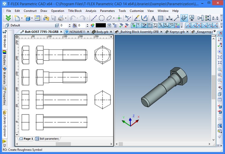
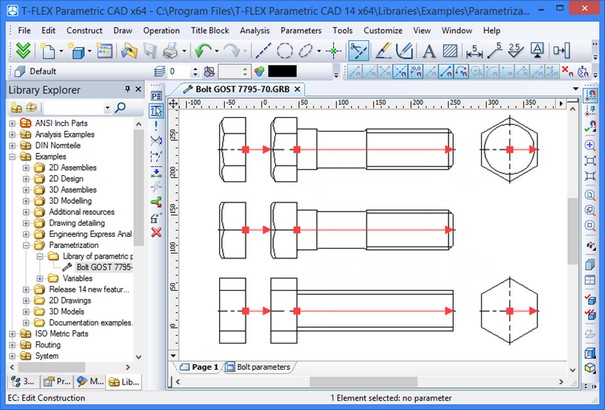
Let's review each step by an example. Consider a bolt GOST 7795-70. The file for this example can be found in the library "Examples" in the folder “T-FLEX Parametric CAD\Libraries\Examples\Parametrization\Library of parametric parts creation\ Bolt GOST 7795-70”. The parameters of this bolt should update from the database depending on the input diameter and length. The bolt has several implementations. Both the drawing (the three views: front, left and top) and the 3D model should adjust to each implementation. The bolt will be used as a fragment in other drawings.
Creating a database
At the step, you need to create an internal database to pick the values from.
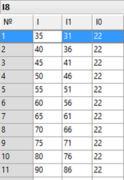
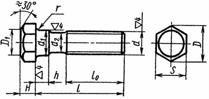
First, you need to decide, which will be the driving parameter. In our case, the candidate parameter is the bolt thread diameter. Therefore, the bolt diameter is entered in the first column, followed by all the rest of the parameters (except the length). The names of the database columns (and the database itself) should be made descriptive, so that later, when creating variables, you could easily remember which column relates to which parameter. However, too long column names are not recommended either. A good strategy is to name the columns according to engineering standard notations adopted in your industry. In our example, the thread diameter is named d, the bolt head size - S, etc.
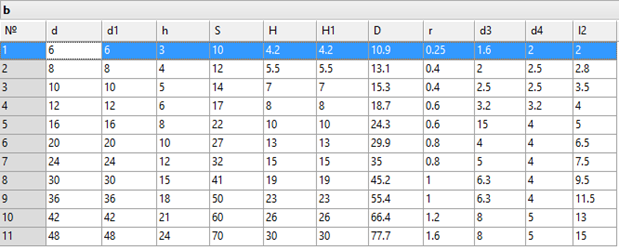
In our example, the input bolt length must be rounded to the nearest standard length. We should also account for the fact that the set of standard lengths is different for each diameter. For example, the bolt diameter of 6 mm corresponds with the length of 30 mm, while the bolts 12 mm in diameter have minimum length of 45 mm. Besides, depending on the selected bolt length, two additional parameters are defined: l1 and l0. We recommend creating separate databases of lengths for each diameter. The suggested database names are l6, l8, etc. The letter l, as in "length", refers to the databases of lengths, while the number stands for the respective diameter. Once the databases are created, proceed to the next step. |
|
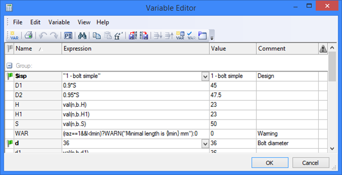
Creating variables relying on databases
At this step, we need to create variables that would be used for building the parametric drawing and the 3D model. We recommend using descriptive names for the variables.
First, define the driving variables for the rest of dimensions, whose values need to be defined when assembling the part. In this example, those are the diameter, the length and the implementation (see below). If a variable has a set of standard values, it is helpful to create the predefined list of values for convenient and quick input. The list of values can be created based on an existing field in the database. Upon creating a variable, it is a good practice to put a description in the comment field, so that another person can easily decide on what data to input, when working with this document.
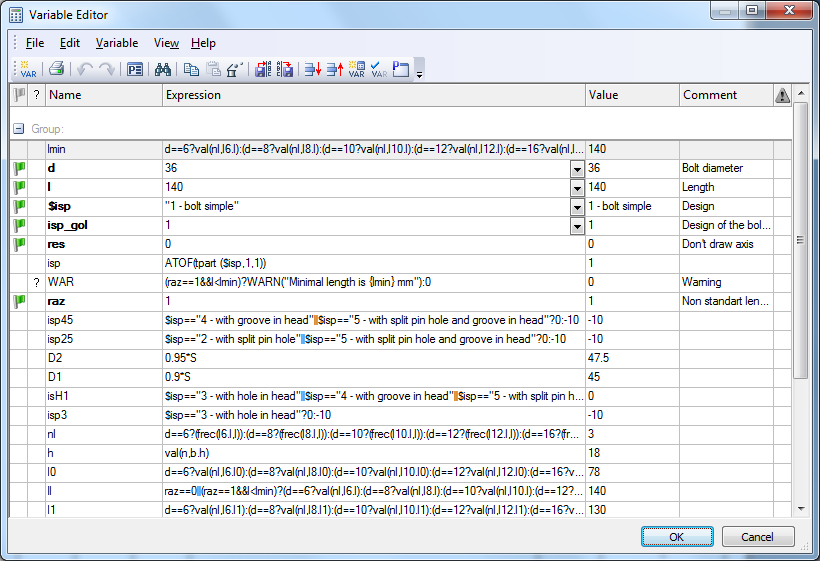
Next, we need to create variables that keep track of the database record number from which the values are taken. Such variable value can be read by calling the function rec or frec. For the functions description, refer to the chapter "Databases". In this example, we need two such variables: one (the variable n) for accessing the values dependent on the bolt diameter from the respective database, and the other (the variable nl) for maintaining the value of the length. The challenge here is that the second variable should be assigned an appropriate record number across different databases (depending on the diameter). Besides, one should keep in mind, that the input length might not be always correct, as the designer of the part could enter a nonstandard bolt length. Therefore, the value of the variable nl can be described by the expression: d==6 ? frec(6.l,l) : (d==8 ? frec(l8.l,l) : d==… ), that means, if the variable d (diameter) is equal to 6, then do the search for the record number in the database number 6, otherwise, if the variable d is equal to 8 - then do the search for the record number in the database named l8, and so on over all databases.
Next, create the rest of the variables. Their values are accessed by calling the function val based on the value of the variable that keeps the record number of the database (those are - n and nl). The value of the bolt length (ll) will be defined by the expression: d==6 ? val(nl,l6) : (d==8 ? val(l8.l,l) :d==… ). The meaning of this expression is similar to that of the variable nl described above.
The bolt has several implementations. The drawing should adjust, depending on the implementation. This can be fulfilled by setting, when necessary, the level of certain drawing elements below the displayable threshold. We need to create special variables for this purpose (separate for each implementation). By default, the displayable elements have level from 0 to 127. If the level of an element is below zero, it is not displayed. Consider, for example, the variable imp25 that defines the level of the elements visible only in the implementations number two and five. It is equal to 0 when the implementation (defined by the string variable $imp) is equal to "2 - with pin hole" or "5 - with pin hole and groove", and is equal to -10 in all other cases: $imp=="2 - with pin hole"||$imp=="5 - with pin hole and groove"?0:-10.
Special functions (WARN and ERROR) are provided in T-FLEX CAD for prompting the user about errors when variables take certain inadmissible values, and request inputting different value. For example, if a non-specified bolt length is encountered, you can force the message: "The input bolt length is not standard". This is done by calling the function: WARN("The input bolt length is not standard").
Once the necessary variables are created, you can proceed with creating the drawing and the 3D model.
Creating parametric drawing and 3D model
When using a library element is a fragment, it is often necessary to insert just a portion of the drawing. Anticipating that, you can predefine several new layers. Use descriptive layer names to make it easy to understand which portion of the drawing belongs to which layer. In our example, we need to create three new layers. Let's name the layers according to their purpose: front view, left view and top view. During creation, all elements can be placed on any layer, for example, on the layer "Main". Once the drawing is ready, simply select the desired portions by box and modify the layer of those elements as desired.
Some elements of the bolt (for example, the pin hole) may or may not be displayed, depending on the implementation. At the previous step, we created special variables for this purpose. The variable imp25 is equal to 0 whenever the implementation is equal to "2 - with pin hole" or "5 - with pin hole and groove". In any other implementation, the variable is equal to -10. If an element is to be displayed only in the implementation 2 or 5, its level must be defined by the variable imp25.
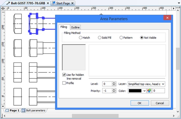
To make sure that in the assembly drawing the bolt is properly displayed in the bolted joints, to each view of the drawing let us add hidden hatches with the activated option of suppressing the hidden lines.
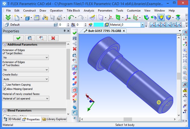
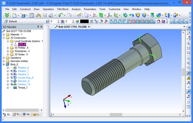
Upon completing the 2D drawing, proceed with the 3D model. Suppose, your 3D model is required to undergo changes depending on some parameter. It is not solely the model dimensions that could change. Some features may appear or disappear in the model. In our example, such a feature is the pin hole. The easiest way to achieve this is by suppressing a certain operation. This can be done using the same variables as when defining the level of the respective features on the drawing. What exactly can be done in this case? The pin hole is created as follows. First, an rotation was made, creating a cylinder. Next, a Boolean subtraction was done of the cylinder from the bolt stem. The rotation operation can be suppressed as follows. Among the "Rotation" operation properties, assign the parameter "Suppress" to the variable imp25. The extrusion operation will be suppressed when the variable is not equal zero (that is, when the implementation is not equal 2. To avoid a system error when creating a Boolean with an empty member, set the flag "Allow missing operand" among the Boolean parameters.
On the resulting body of the bolt the user should put a thread. To achieve this, let us use the command “3AT: Create thread”.
The drawing and the 3D model of the future library element are completed. Next, let us create fixing vectors and the special coordinate system for fixing the created document in the assembly drawing. They will be used for inserting the given document as a fragment into the assembly.
Creating Fixing Vectors and Coordinate System for Fixing Fragment in Assembly
In our case, the fixing vector will be used when the library element is inserted as a 2D fragment into the assembly drawing. To use it as a 3D fragment, it is necessary to create a special local coordinate system (3D analog of the fixing vector) which will be used for fixing the fragment in the 3D assembly model.
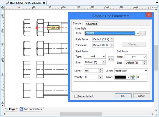
For our drawing of the bolt let us create several fixing vectors, each for inserting a certain layer. Among the created vector properties, the flag is checked “Draw only marked”, and the layer is marked that should be displayed upon the insertion. The same vector names as the layer names are used for clarity.
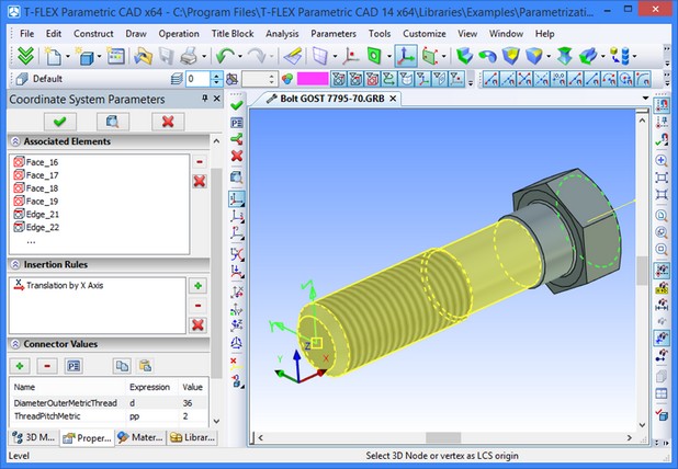
On the 3D model of the bolt, let us create LCS for fixing a 3D fragment.
The position of the fixing vectors and the coordinate system is determined by the main surface (the contact surface between the bolt and other parts). This is the surface of the bolt head base. When inserting a fragment, the contents of the fragment folder are displayed in the left portion of the coming up dialog box. If the flag is set "Show icons", then the drawing slides (icons) are displayed next to the file names. We recommend creating slides for the drawings, to insure easy selection for assembling.
The slide can be created using the command "Tools| Special Data| Preview". Upon entering the command, select the item "Create Raster Preview as Windows Bitmap (BMP)", press the graphic button [OK] and select the portion of the drawing that you want to put on the slide. After this, proceed to the next step.
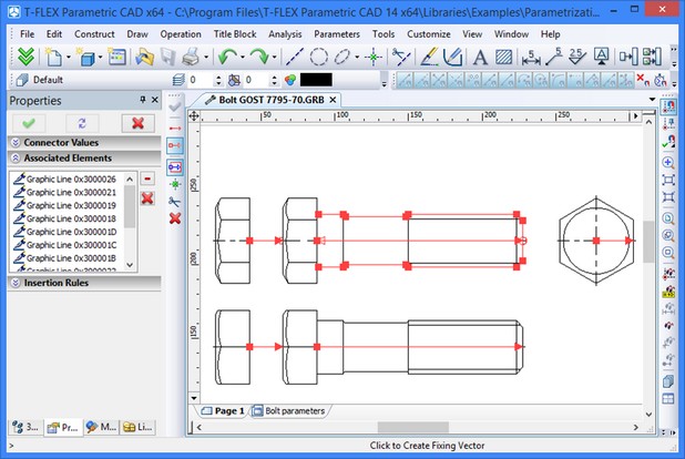
Creating Connectors
In the assembly drawings, other fragments, for example, a fragment-nut, will be attached to our library bolt element. Let us create conditions for a quick “connection” of other fragments: let us add connectors to created drawing and 3D model, and also assign connector’s values to external bolt variables (for a quick specification of the values of the fragment’s variables upon inserting a fragment into the assembly).
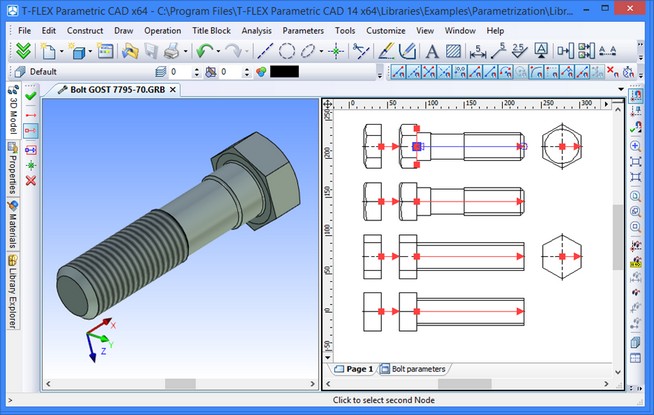
For the drawing, let us create four 2D connectors – for two front views (standard and simplified) and for two top views. For creating a connector, the command “FV: Construct Fixing Vector” can be used.
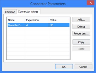
Let us specify the named value “DiameterOuterMetricThread” for all 2D connectors. This named value will pass the magnitude of the bolt’s diameter to the fragment (nut) being attached. As an expression for the named values of all connectors, indicate the variable “d”.
Note that for the successful use of the connectors, upon creating the fragment of the nut it is required to indicate the connector’s named value “DiameterOuterMetricThread” in the properties of the variable controlling the nut’s diameter.
For created connectors, let us indicate graphic lines, as associated elements, on the corresponding views of the bolt – this will simplify fixing to the given connector.
Also, for 2D connectors it is required to specify «Insertion rules». When fixing a nut to the bolt’s connector, it is usually required to specify additional translation along the X-axis of the connector.
By the same principle, let us create 3D connector on the 3D model. For the 3D connector let us create two named values: “DiameterOuter-MetricThread” (bolt diameter) and “ThreadPitchMetric” (pitch of the bolt’s thread).
Having created connectors, we prepared a basis for convenient fixing of other fragments of the assembly to our fragment. Next, let us return to the variables editor of our model and specify the following value of the connector: “DiameterInnerMetric” for the variable “d”. The same named value was specified for the connectors entering the library of openings. As a result, when the fragment of the bolt is inserted into the assembly by means of fixing to an opening’s connector, the actual bolt diameter will be defined automatically.
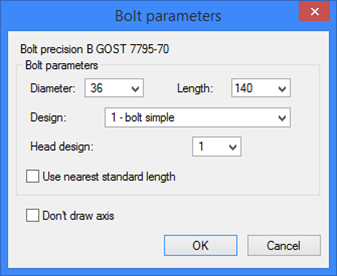
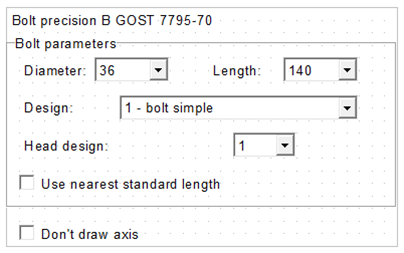
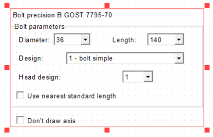
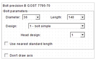
Creating dialog box
At this step, we will compose the dialog box that will be used for inserting the current drawing as a fragment. Each time when assembling a drawing (model), the user will be getting a dialog box containing standard Windows elements (input boxes, pull-down lists, etc.), helping easily and quickly defining the parameters of the fragment being assembled. Creating such a dialog box is relatively simple. First, create a new page to hold the control elements. To do this, lunch the command "Draw|Control" and select the automenu option Some variable can have only two determined values. To work with these variables, it is convenient to use a "Yes/No" switch element. When creating such an element, you define the variable values for the cases when the switch is on and off. When specifying the text displayed on controls, it is possible to use variables. This will allow for changes in the text contens of the dialog according to selected bolt’s parameters. For example, in the dialog of our bolt, the text for one of the controls of the type “Static text” is set in the following way: “Bolt {$ispsp}М{dd}{$polesp}%%042{ll}{$klprsp}{$mmat}{$Pocrnom} GOST 7795-70”. Next, change the page size (this can be conveniently done by the command "Customize | Page size") to make its size equal to the size of the dialog box. After that, start the editing mode of the control elements and define the order of the control elements. The order of the control elements determines their appearance in the dialog box and their activation order when using the <Tab> key. It is recommended to place static text first, followed by the control elements bound to the variables, in the order that provides easy switching between them. |
|
Adding an element to library
The last step to be made is adding the element you've created to the library, and, if necessary, creating a new library.
To add an element to an existing library, copy the created element to the folder on your hard disk, where other library bolts are stored. In this case, the element will automatically appear in the library after restarting the application. You can also create a new library. When doing this, carefully check every step, as in the following example. Suppose, you need to move a library to another file system, where the root folder name is D: rather than C:. If the full path was specified when adding the element to the library ("C:\…"), the application will not find the file, and therefore, you will not be able to insert the fragment using the library.
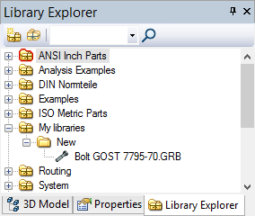
To avoid this, use the relative rather than the full path when adding an element to a library.In this way, the path will be defined with respect to the configuration file that determines library contents. Besides, your created element should be placed "deeper" then the configuration file. Suppose, we are to create a new library for our newly created bolt. The folder of this drawing will be “C:\Program Files\T-FLEX Parametric CAD\Libraries\My libraries\New”, while the configuration file will be located in the folder “C:\Program Files\T-FLEX Parametric CAD\Libraries”. When creating the library, specify the relative path with respect to the configuration file rather than the full path: “New”.
Now, we need to fit the drawing with the data necessary for supporting the BOM creation mechanism in T-FLEX. In the "Product structure" window select the group to include the part into. Define the name, material, weight and other parameters.
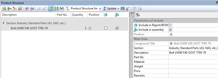
Since the bolt name is supposed to change depending on its parameters, let's use variables for defining the name. The bolt name will be: Bolt{imp}М{d}*{ll} GOST 7795-70. In the formatted BOM, the actual values will replace the variable notations {imp}, {d} and {ll}. The weight and material can be defined in the same way.
Finally, we would like to mention that the described procedure is just a recommended technique, rather than a strictly determined sequence of actions.