New Tools for Parametric Drafting


New Tools for Parametric Drafting |
|
In the new version, mechanisms of parametric design, which are the basis of the functionality of the system, were improved.
For a long time, the only parameterization mechanism in T-FLEX CAD was the mechanism based on the history of the constructions. To form the geometry of the drawing, the construction lines and parameters of these lines were used.
Now, along with this mechanism, the mechanism of variational parametrization is available to users. The new mechanism allows you to set geometric and dimensional dependencies directly on the elements of the drawing.
First, the mechanism is convenient for quickly creating profiles of future 3D‑ models.
A large number of drafting commands, which were previously intended for nonparametric drawing, were updated to support the new parametric drafting mechanism.
Variational Design. New Possibilities of Parameterization
New variational design features are built into existing parameterization mechanisms and tools, providing users with even more flexible parametric capabilities.
Thanks to the tools of variational design, it became possible to define the relationships between geometric elements (lines, circles, curves, etc.) by means of constraints -geometric and dimensional relations.
The use of constraints makes it possible to eliminate dependence on the order of the constructions, giving the designer greater freedom when working on projects. To set or remove constraints between elements, you can change the values of the model parameters at any time while designing.
Freedom in setting constraints also allows you to deal with cyclic dependencies. Geometric elements do not have rigid hierarchical dependencies and therefore restrictions can be freely assigned between elements in any order.
The user is given the opportunity to work with not completely defined parametric drawings.
In addition, variational design allows you to create parametric drawings and set the initial data for 3D modeling without the use of construction elements.
It should be noted that the "classical" mechanism for T-FLEX CAD parameterization based on the construction lines, and the new one, based on the constraints, have their distinctive advantages and features that should be taken into account when using.
Both technologies can be combined in one model and even on one page, using the same additional parametrization tools: variables and expressions, databases, user dialogs, parametric and adaptive fragments, etc.
Constraints (geometric and dimensional) can also be created between construction lines and image lines.
Design based on the history of constructions |
Variational Design |
The position of the geometric element relative to the previously constructed elements is determined when it is created |
The position of the geometric element can be set or changed at any time by means of constraints |
Cyclic dependencies are not possible (previously constructed elements can not depend on the elements constructed later) |
Circular dependencies between elements are permissible |
The parametric model is always completely and unambiguously defined |
The model may not be completely defined, which on the one hand makes it convenient to modify it, but on the other hand it can lead to unpredictable results upon parametric changes |
The recalculation of the model requires only a single passage, which makes it possible to quickly calculate models with a large number of elements |
The recalculation of the model requires a specialized calculation of the constraint system, which limits the complexity of the model and the computational speed |
Uses the construction elements on the basis of which the image lines are created |
Does not require the use of construction lines. Dependencies are added using constraints and control dimensions. |
Variables are used when specifying parameters of the construction elements |
Variables are used as values of control dimensions, as well as for suppression of constraints and control dimensions for the purpose of qualitative changes in the parameterization scheme |
The new mechanism of variational parametrization does not compete with the long-term successful practice of parameterization mechanism based on the history of constructions. It is a complement to the existing mechanism, which allows:
- to solve more conveniently a certain class of parametric problems, including situations where the problem is not completely defined at the initial stage;
- to work in the familiar style for users who have moved from other systems;
- to avoid usage of construction lines for those who, for whatever reason, do not want to use them.
The existing parametrization mechanism based on the construction lines continues to be the key functionality of T-FLEX CAD and will continue to evolve in the future. In particular, a number of significant novelties on it were added in the 16th version. Read more about them below.
It can also be noted that T-FLEX CAD is by far the only system on the market in which two parametrization mechanisms are realized at once, and they coexist harmoniously with each other and can even be used simultaneously within the framework of one project. This approach provides users with the maximum level of flexibility in terms of the use of certain parametric tools, taking into account the nuances of implementing specific projects and personal preferences.
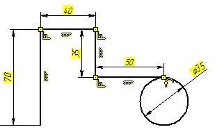
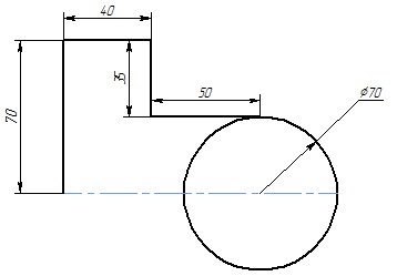
Let us analyze the main points of work with the new mechanism on a simple example.
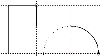
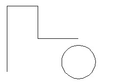
First, you need to create the basic geometric elements of the future model using the Sketch command.
The mechanism does not depend on the build sequence, so you do not have to immediately specify the relationships between the drawing elements.
Constraints and dimensions for created items can be created automatically. Automatically created dimensions and constraints can be replaced by others. The way to create them will be described later in the text.
Constraints are used to create relationships. They determine which elements are parallel, which have an equal radius, etc. Thus, the constraints set the geometry of the model and allow it to be controlled.
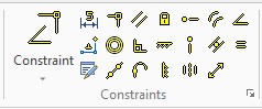
To create a constraint, select it in the Ribbon panel or call the command SC: Constraint and specify the elements for which a constraint will be created. Constraints of the same type are created continuously, i.e. you only need to select new elements to create constraints.
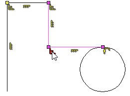
For example, to create a tangent, you need to specify a segment and a circle.
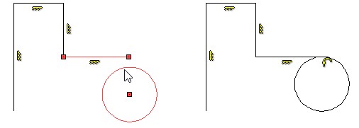
To create a coincidence for the two lines, you must point the cursor to the line and then select a point that will coincide the point of the other element. This is important for creation of constraints, because if you select just two lines, the system cannot accurately determine the future geometry.
The mechanism of snapping to characteristic points of elements is realized. Characteristic points can be used to create constraints. For example, you can fix a circle by selecting a characteristic point of its center.
Description can be found in the section "Snaps".
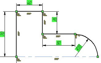
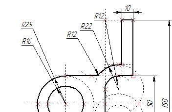
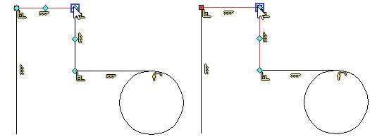
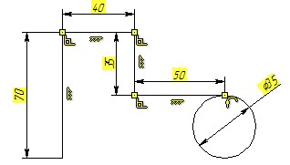
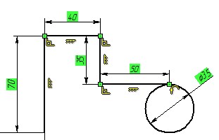
In the example, horizontal ![]() , vertical
, vertical ![]() , perpendicular
, perpendicular ![]() , coincidence
, coincidence ![]() and tangency
and tangency ![]() constraints were created. They are all displayed on the drawing in the form of icons next to the elements.
constraints were created. They are all displayed on the drawing in the form of icons next to the elements.
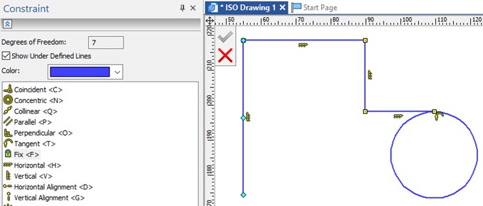
Command SC: Constraint allows not only to create constraints, but also provides information about the drawing
The Degrees of freedom field shows how many degrees of freedom remains for the drawing elements.
You can select all elements that are not fully defined using the Show Under Defined lines option.
When you hover over the icon, the elements, for which constraints were created, are highlighted. You can delete the constraints by selecting the icon and pressing the <Delete> key.
To simplify the design process, the Auto Parametrization ![]() option is available on the filter toolbar. If it is active, the main constraints, such as parallelism, perpendicularity and tangency, will be created automatically by the system.
option is available on the filter toolbar. If it is active, the main constraints, such as parallelism, perpendicularity and tangency, will be created automatically by the system.
Constraints allow you to determine the position of the elements only partially. If you try to move the elements, they will not change the position relative to each other, however their size will change.

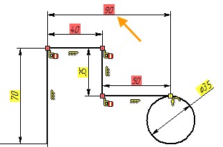
In order to fully define the drawing dimensional constraints should be created in addition to geometric constraints.
Dimensional constraints are created using the command D: Dimension.
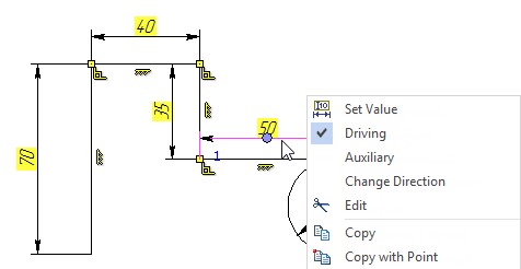
To increase the convenience of creating driving dimensions, the ability to immediately edit the dimension nominal without leaving the command is added. To do this, the Edit driving dimension value on creation option must be active in the dimension parameters.
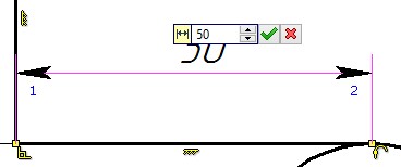
When the dimension is created, you can enter the nominal edit mode by clicking on the nominal.
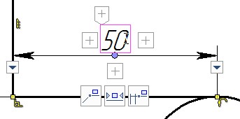
To work with the mechanism of variational design, the "Driving Dimension" was introduced. It is responsible for the geometry shaping, so when you change it, the element changes.
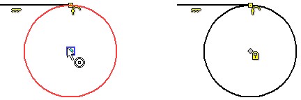
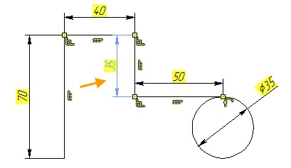
The values of the control dimensions have background. The background color of the dimensional value shows different states of dimension and geometry in general:
The system is under defined - the background is yellow. If the system is under defined, then some elements still have degrees of freedom, so they can be changed and thus affect the overall geometry of the model.
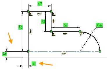
The system is defined - the background is green. If the system is defined, then the elements do not have degrees of freedom, and the resulting geometry can not be changed. When the drawing is finished, it is recommended that the system is defined.
The system is over defined, or there is an error setting the value of the driving dimension- the background is red. This is the case when user has created unnecessary driving dimensions for the element, or has set dimensions, the values of which cannot be provided.
The option ![]() allows you to always create control dimensions in the command D: Dimensions.
allows you to always create control dimensions in the command D: Dimensions.
Also the "Auxiliary dimension" type is available for lines. Auxiliary dimensions can simultaneously be driving, but they are not printed and can be hidden in the scene.
You can change the dimension type in its context menu. When you manually set the dimension value, it automatically becomes driving.
The user can also create a dimension relative to the origin of the drawing. Sometimes it is necessary to completely define the drawing.
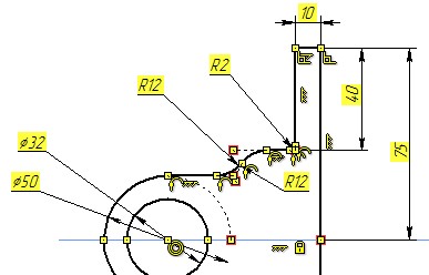
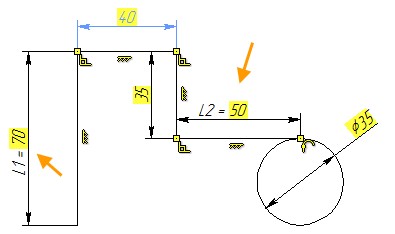
With the help of driving dimensions, the user can control the parameterization of the drawing. To do this, you must specify a variable or an expression for the dimension value. The name of the entered variable is displayed before the value of the dimension nominal.
Dimensions for the elements can be created automatically. To do this, enable the Create Dimensions Automatically ![]() option on the filter toolbar.
option on the filter toolbar.
New dimension types that allow you to control parameterization using the new mechanism were added. More details about these dimensions can be found in the section "Dimensions".
Updated set of Commands and Drawing Tools
Not only dimensions can be auxiliary, but also other elements (lines, circles). They are not printed and can be hidden using the Hide constructions ![]() option.
option.
It is important to remember that the auxiliary lines are full-fledged elements of the drawing, so constraints and dimensions are created for them too.
If necessary, all constraints and background for the driving dimensions can be hidden by the option Show/Hide Constraints ![]() .
.
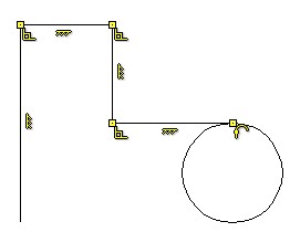
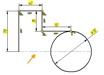
To complete the drawing, you can use the Trim ![]() command to delete all unnecessary constructions.
command to delete all unnecessary constructions.
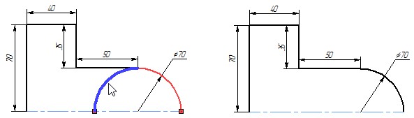
A filter of automatic creation of constraints and dimensions is also available for the trim command.
Constraints for the finished drawing can be created automatically. To do this, use the Infer Constraints ![]() command. This is a convenient tool for quickly creating a large number of constraints.
command. This is a convenient tool for quickly creating a large number of constraints.
The command displays the number of degrees of freedom and you can select under defined elements with color.
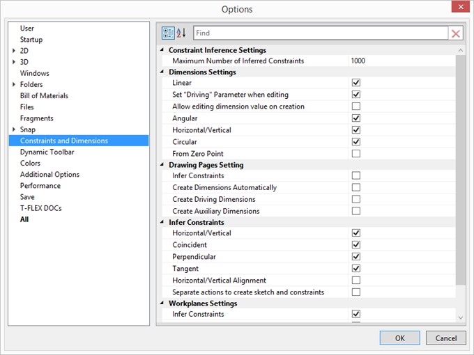
In the Constraints and Dimensions sections, you can manually specify, which constraints and dimensions will be created automatically.
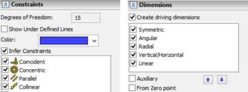
You can assign a creation priority for dimensions. The Auxiliary option allows you to make all created dimensions auxiliary, and the option From Zero point allows the system to use the origin to create dimensions.
In the Options dialog the Constraints and Dimensions tab is available. User can specify parameters for the automatic constraints creation on it.