Working with Assemblies


Working with Assemblies |
|
When developing a new version of T-FLEX CAD, great attention was paid to the management of the objects geometry to improve the convenience of working with complex assemblies and details. Increased efficiency of the old mechanisms and added a number of new features.
●The mechanism of borrowing geometry for designing elements in the assembly has been improved. Now user can not only create parts in the context of the assembly based on the existing geometry, but even upload this geometry to a separate file and track its change. This opens up wide opportunities for teamwork on complex projects;
●Improved assemblies navigation. The model tree and the Assembly Structure window now displays information about all the elements of the subassembly at all levels. User can immediately switch to editing of any of these elements right in the context of the assembly.
The system implements a new mechanism of reference elements, which allows you to borrow a three-dimensional geometry of objects for subsequent operations. The basic elements of the model (3D nodes, coordinate systems, workplanes, 3D profiles, 3D paths, bodies of various types), and topologic elements (edges, faces, vertexes) can be borrowed.
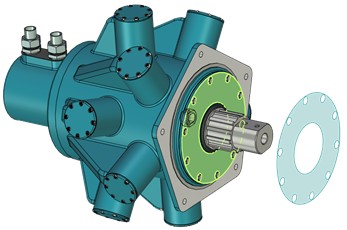
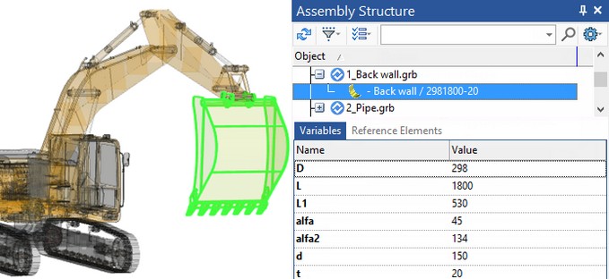
In the example below, the face of the excavator body was borrowed to snap the hydraulic motor model.
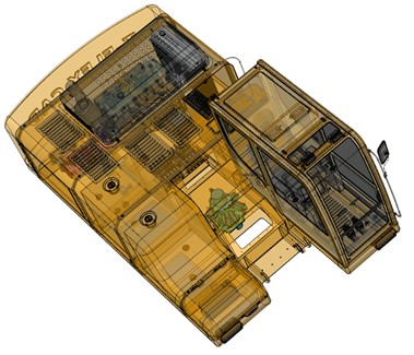
If this face changes, or if you need to move the motor/excavator body in the scene, users will not have problems with object snapping. The body and the hydraulic motor will move and change independently of each other.
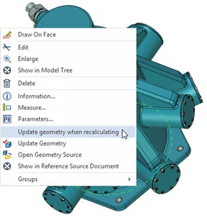
To update the face of the body to which the motor is attached, you can use the Update geometry when recalculating.
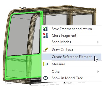
The Create Reference Element command appeared in the system. It creates an object of the appropriate type, which stores a copy of the geometry of the source element. This copy "remembers" the information about the source, and its geometry can be updated either automatically or manually, depending on the corresponding parameter of the reference element.
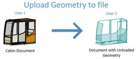
For example, you need to unload the cabin to fill it with equipment. One user develops the cabin, and other users do not have access to this file.
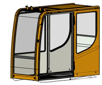
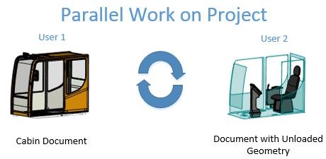
The geometry of the cabin can be uploaded to a separate file so that several users can work in parallel. To do this, a fragment is created in the context of the assembly, and reference elements are unloaded into it.
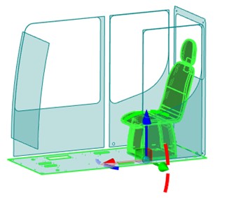
On the basis of these unloaded elements another user can create equipment in the cabin, having full data on the current dimensions of the cabin. In this case, it is possible to snap to the unloaded geometry and update the unloaded geometry in accordance with the changes in the source file of the cabin.
The mechanism of reference elements allows to solve the problems with the development of complex assemblies. For example, the user can borrow the geometry of elements from the elements of higher-level fragments in the assembly structure, or from fragments located in "parallel" subassemblies.
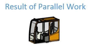
Example of the cooperative work scheme:
A geometry is unloaded into a separate file in the context of the assembly.
The user can receive changes of the uploaded geometry from the source document or update the source document in accordance with the changes in the uploaded file at any time.
The mechanism of reference elements ensures that there is no loss of borrowed geometry. It also ensures integrity of the model in case of absence of the source object of the original geometry. For example, when you rename or delete a fragment file that is the source of referential geometry, when body recalculation errors occur, etc.
The introduction of the reference element mechanism allows T-FLEX CAD to be taken to a new level and greatly simplifies the design of complex products for users.
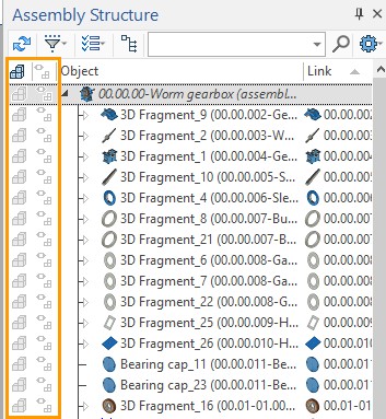
The External Links window has been renamed to the Assembly Structure window and new features have been added to it. The window provides functionality for managing the multi-level structure of the assembly model. Information is presented in the form of a tree structure. When selecting fragments, a list of variables for these fragments and referential geometry are displayed.
For fragments of any level, the command Open in Context is available. You can also go to editing in the context of the assembly by double-clicking on the fragment.
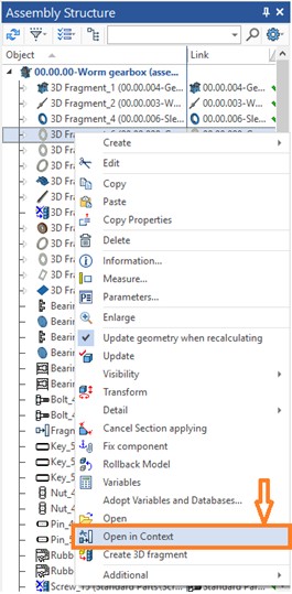
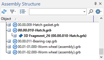
All fragments of the upper level, the assemblies of which includes the fragment edited in the context of the assembly will be marked in italics. This will simplify the search for the edited fragment.
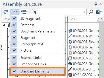
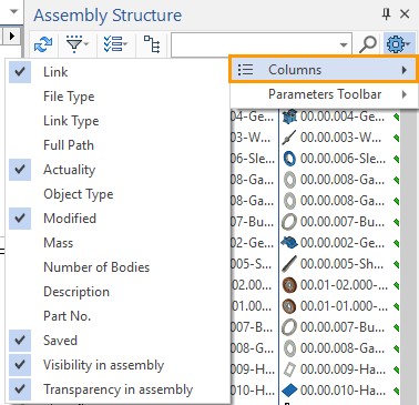
The possibility to hide standard elements in the list was added to simplify designing of large assemblies.
There is also a possibility of filtering assembly structure elements by types and other characteristics.
All geometry borrowed from other files is displayed on the Reference Element tab.
The Create 3D Fragment command is now available on each level of the assembly structure. The command allows specifying general parameters of a new assembly component and, if necessary, begin its editing in the assembly context.
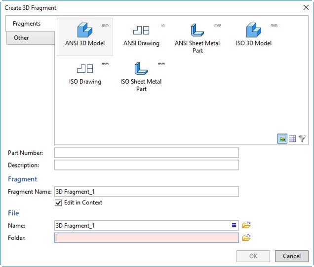
The updated dialog of 3D fragment creation allows selecting of a prototype based on which a new fragment document will be created. You can also specify its part number and description, specify a fragment name in the assembly.
User can select columns that will be displayed in the window.
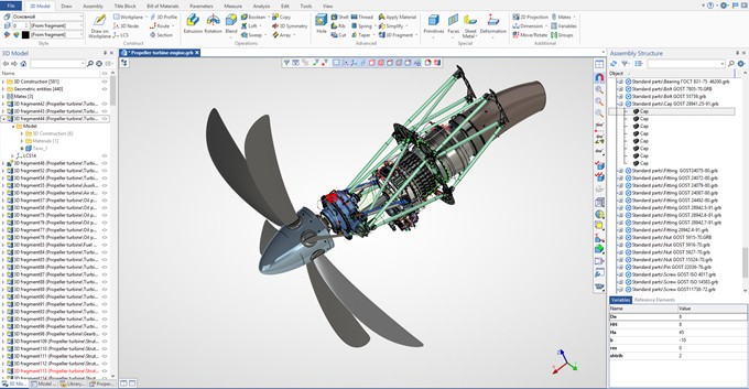
Displaying the Assembly Structure in the "3D Model" Window
The 3D Model window has been refined to provide control of the assembly structure. Now the window displays the structure of all fragments and subassemblies that are included in the assembly. To see the structure you need to open Model folder of subassembly fragment.
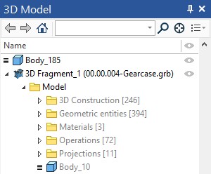
The structure view is available for all levels of nesting.
Marking of bodies and operations also occurs at all levels of nesting.
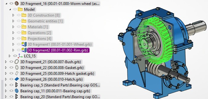
For items in the "Model" folder, the Open in Context command is available. If you call the command for a fragment or an operation, the system will go into editing it in the context of the assembly.
Now all the fragments and operations can be edited directly in the assembly.
The number of objects in a folder is displayed in the model tree next to the folder name.
Visualization upon Designing in Context of Assembly
When a fragment model is edited in the context of an assembly a geometry of the assembly model becomes semitransparent by default. The system allows managing the visualization. An assembly geometry can be displayed in the context of the assembly without changes or be hidden.
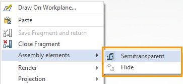
The Assembly structure window allows managing visibility and visualization mode of all fragments beyond the edited model. It regards to the assembly elements on the levels higher or lower than the model being edited as well as the fragments on the same level with it. The special commands and columns in the assembly structure are used for it.