New Capabilities of T-FLEX CAD Version 16


New Capabilities of T-FLEX CAD Version 16 |
|
T-FLEX CAD 16 offers various new features and improvements, many of which are implemented in accordance with the requests of users. Among them - new possibilities for parametric drawing, effective tools for working with complex assembly products, new technological solutions for electrical engineering and sheet metal, design in virtual reality and much more.
New Tools of Parametric Drafting
New mechanism for creating parametric drawings based on variational parametrization is added. It allows you to create parametric drawings and create profiles of future 3D models without the use of construction lines. For the sketch lines, you can now apply various geometric and dimensional constraints that determine the geometry of the project. The new mechanism is another way of defining the relationships of the drawing elements along with the existing mechanism based on the construction lines.
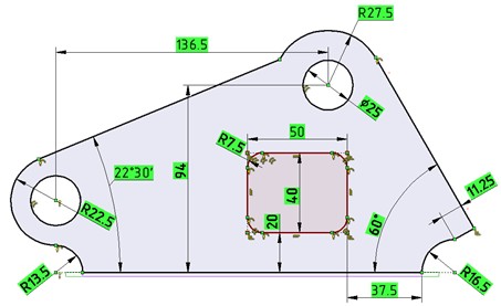
With this way of defining relationships users do not need to think in advance the order of lines creation, since their position and relations to each other can be changed at any time.
Both mechanisms can be used both individually and in combination, providing users with a wide range of options for solving problems of different nature.
Flexibility and Efficiency when Working with Large Assemblies
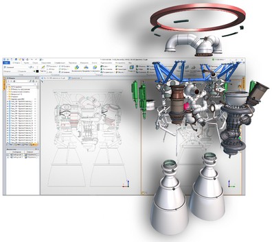
Improvements in the new version for working with assembly models will be of great use in the design of complex products, solving common problems of such industries as automotive, aerospace, shipbuilding, engineering, etc.
New tools and improvements to existing assembly modeling mechanisms provide efficient ways to work with any objects throughout the entire hierarchy of a complex product, edit parts directly inside the assembly itself, use geometry of any objects as the basis for new parts.
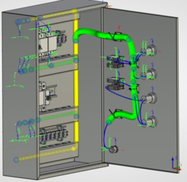
New Add-on Application for Electrical Design
T-FLEX Electrical - a new fully integrated add-on application for T-FLEX CAD. It provides a wide range of tools for development of electrical systems: from construction of two-dimensional circuits to the placement of 3D models of electrical components, creation of wires, cables and connections, harnessing and generation of fully integrated specifications, which include both mechanical and electrical parts.
Design Using Virtual Reality
T-FLEX VR is a new integrated application, which allows you to work in T FLEX CAD 16 using virtual reality technologies.
Users can view models using the virtual reality helmet, as well as move objects in the scene and invoke commands with manipulators.
The results of actions are displayed in real time thanks to synchronous updating.
Sheet Metal Design
Tools for designing sheet metal parts were significantly improved in the new version.
New operations - "Corner", "Normal Cutout", "Gusset" and «Hem" - were added.
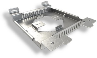
It is now possible to create flanges on a custom 3D Profile. User interface of operations has been updated, new features have been added to the existing commands, a semi-transparent dynamic view has been implemented, and functionality of manipulators has been improved.
Updated Variable Editor
Variable editor now displays expressions on the screen as a whole, highlights the syntax in different colors and helps you find the necessary functions and variables from the list.
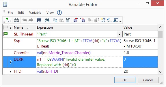
Hints and new functions were added, and much more.
If several documents use the same variables, they can now be stored and updated in one single file.
Detailed information on these and other innovations in T-FLEX CAD 16 will be provided later.
New Possibilities of Parameterization
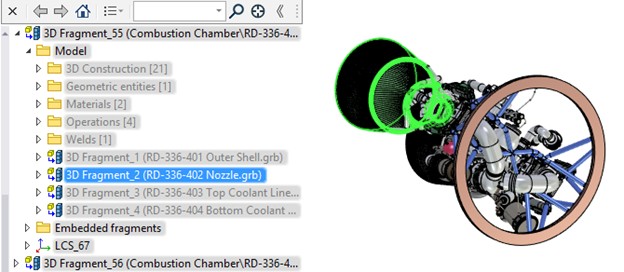
Displaying the Assembly Structure in the "3D Model" Window
Visualization upon Designing in Context of Assembly
3D-path as Intersection of Elements
Building 3D Profiles by Unfolding
Manual Mass-Inertia Characteristics Control
Innovations in Variable Editor
Adopting Variables and Databases
Elements under Cursor Selection