Modeling


Modeling |
|
Interface was improved and intuitiveness of commands implementation was increased for all sheet metal commands.
All dialogs of the commands were updated and unified. Now it is easier for user to find parameters and less clicks are required to create operation.
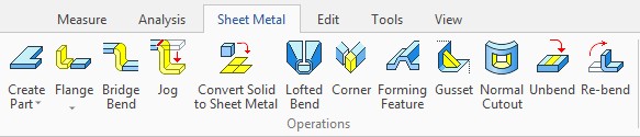
All commands are added to a special Ribbon tab.
A separate command is available for each sheet metal operation. It increased speed of operations creation and model recalculation.
A separate prototype with all required parameters was added for sheet metal parts to accelerate modeling process.
Commands for solving the following tasks were added: corner creation, normal cutout creation, gusset creation, creation of flange using user profile, bridge bend creation, etc.
Suggestions from users were taken as a basis for refining the functionality of sheet metal.
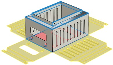
Sheet Part Prototype
A new "Sheet metal part" prototype was added.
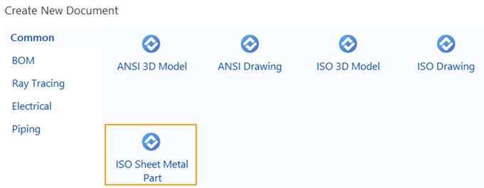
A "Sheet metal" tab is active for the prototype by default. New commands for designing sheet metal parts were added on it.
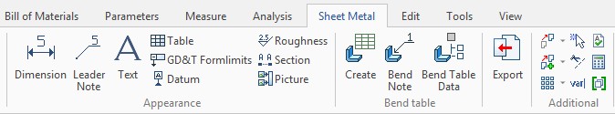
The "Sheet metal" tab on the Ribbon is divided to 2D and 3D parts with set of commands for modeling and drawing design.
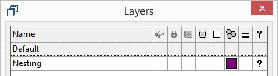
A special "Nesting" layer is created for integration with T-FLEX Nesting. Contours from the layer can be automatically added to the nesting project.
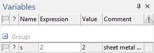
A special variable "s" was added to manage thickness of the part.
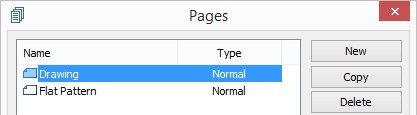
A "Flat pattern" page was created in the prototype.
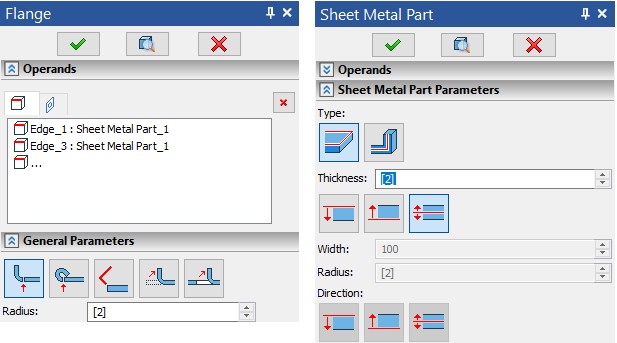
Commands Interface
The Bend command is divided into separate operations - Flange, Hem, Contour flange, Bend, Cut and bend.
Interfaces of the commands have been redesigned to make it easier to create operations.
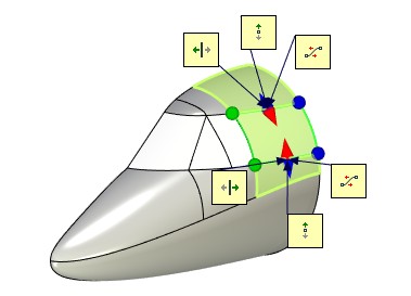
A translucent dynamic preview now available for all sheet metal operations. User immediately sees the result of the operation and can correct it.
Graphic draggers were added to all command of the sheet metal group to specify operation parameters (draggers for length, angle, intends, direction of bends).
Object snaps can be specified for draggers. It means that you can point other objects in the scene, according to which the operation parameters will be set, and snap to the objects. You can delete and reset snaps.
The Operands group appeared in all operations. It allows to manage the model geometry. All operations command are updated. It is easier to find operation in the 3D model tree.
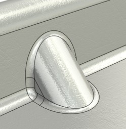
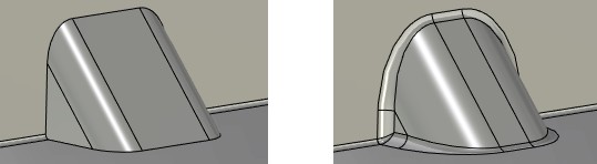
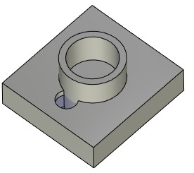
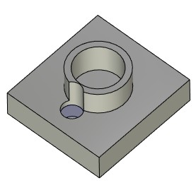
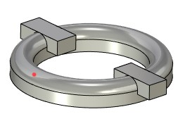
"Gusset" Operation
A possibility of stiffness ribs creation for sheet metal was added. For this purpose, use the command Gusset. The command solves the problem of strengthening the construction.
Each of the ribs is created separately.
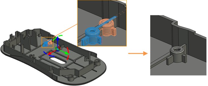
User should select a bend for which a gusset should be created and specify the gusset parameters. You can specify accurate gusset position. To do so, create a workplane and then select is upon operation creation using the ![]() option.
option.
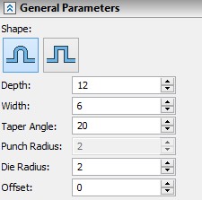
Shape. Specifies shape of the gusset - round or square.
Depth and Width specify main gusset parameters.
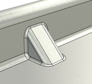
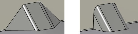
Taper angle specifies an angle of gusset sidewalls.
Punch radius and Die radius. Allow to take technological radius of die and punch into account when creating gusset.
Offset. Specifies position of the gusset. Offset is specified from the closest vertical face. If a workplane was specified upon gusset creation, the offset is calculated according to the workplane position.
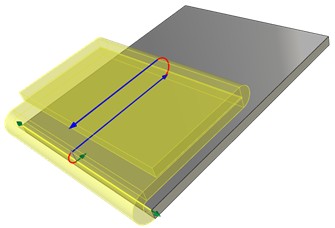
Flanges of Nonrectangular Shape
Now it is available to add flanges of nonrectangular shape to the part using graphic draggers in the "Flange" operation. The functionality solves task of trapezoidal tongues creation.
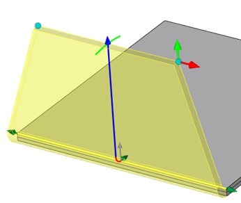
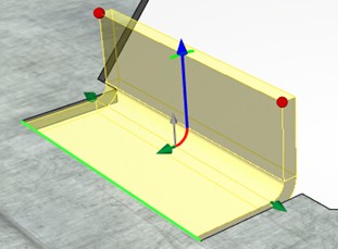
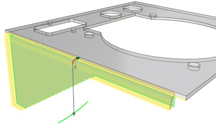
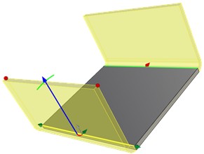
Flanges with Snap to Geometry
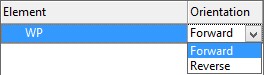
A possibility to create flanges with a snap and orientation according to the already existing geometry was added:
●- translation of flange to the selected plane with tilt angle that is defined by the plane;
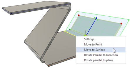
●- rotation of flange parallel to the selected direction;
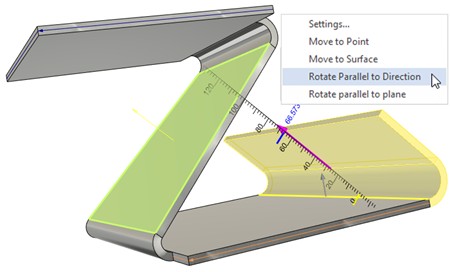
●- rotation of flange parallel to the selected plane;
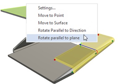
Workplanes, surfaces, body faces are used to orient flanges.
You can manage snaps using context menu, when you click on the appropriate dragger of translation or rotation.
Flanges by User Profile
Now it is possible to create flanges using user 3D profile. You should preliminary create a 3D profile to create such a flange. The profile should lie in the plane of bend edge.
Profiles on the basis of construction lines or sketch lines can be used for the flange.
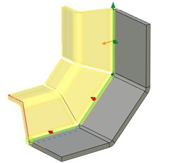
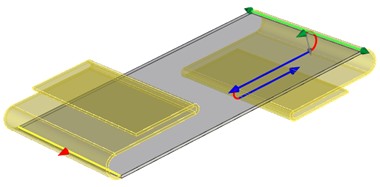
Creation of Flanges on Contiguous Edges
Now it is possible to create flanges and create hem on non-contiguous edges. Direction of each flange can be set individually using graphic dragger. Edges are processed automatically.
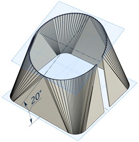
Lofted Bend
Now it is possible to use nonparallel contours in the "Lofted bend" operation.
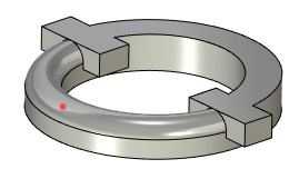
"Corner" Operation
The Corner command allows to create reliefs and specify gaps in raw corners of sheet metal parts. Allows you to close angle for any flange configurations, including inclined flanges.
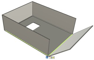
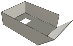
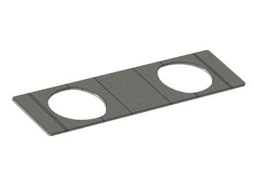
Normal Cutout
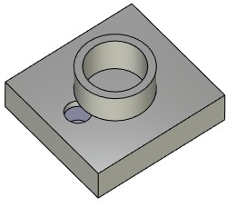
The "Normal cutout" operation allows creating cutout with a gap on the sheet body with sidewalls perpendicular to the main faces.
The operation should be used for cutout creation on the inclined faces. The operation allows to use geometry of the part for cutout creation and to specify gap for the cutout without additional actions.
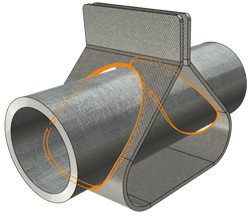
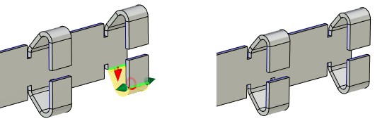
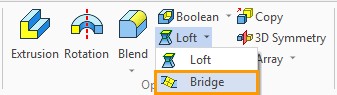
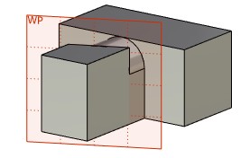
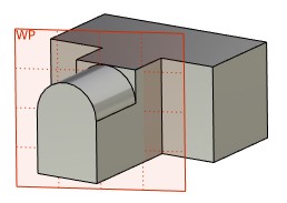
Bridge Bend
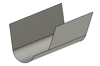
The "Bridge bend" operation allows to create a transitional geometry with the specified bend radius between the edges of two sheet bodies of equal thickness. The edges should be parallel. The result is a new sheet body.
There are two shapes of bridge bend available: Y - shape and Z - shape.
The operation allows to design assembly sheet models. Separate parts can be added to a single body using this operation.
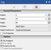
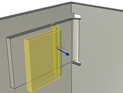
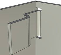
Jog
New “Jog” operation allows you to build a double fold on the sheet body at an arbitrary angle. It serves to couple two parallel flanges.
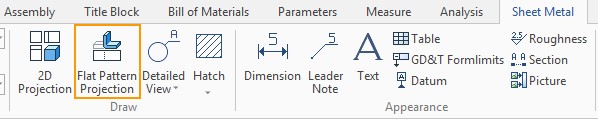
Flat Pattern Projection
The Flat Pattern Projection command allows to quickly create a drawing of a sheet part unfolding.
A designer is often faced with the task of connection of two sets of surfaces using transitional surface. The Bridge command was added to solve the task with minimal number of actions.
The command allows to create a body that used for connection of two other sheet bodies or faces of solids.
You can specify a degree of continuity for the bridge: "surface (G0)", "tangent (G1)", "culture (G2)".
You can control the position of the bridge edges by using draggers in the scene or fields in the options dialog.
You can sew the bridge to the source bodies, or you can create a bridge as a separate body.
The following features were added to the Shell command:
●Option for automatic edge blending;
●Option for overlapping faces processing;
●Possibility to create shells on the basis of other shells with option to include or exclude additional faces;
●Draggers and dynamic preview of changes.
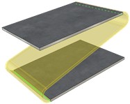
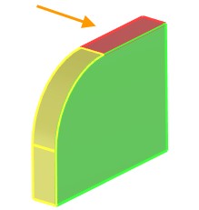
Blending of Convex Edges
The option Blend convex edges was added. The option specifies blending of convex edges that appeared in the direction of faces offset. For example, if the shell is created inside the inner convex edges will be blended as on the picture below.
The value of blending radius should be inserted in the Blend radius field.
Face Extension Type
The Face extension type option manages processing of the overlapping faces, which appears upon shell creation.
The system processes overlapping faces independently in the Auto mode.
In the Extend moved mode the priority goes to the moved faces. Fixed faces are processed according to the geometry of moved faces.
In the Extend fixed mode the priority goes to the fixed faces. Moved faces are processed according to the geometry of fixed faces.
Inclusion and Exclusion of Faces
A possibility to include and exclude faces for part of the model if the main model is a thin-walled body was added.
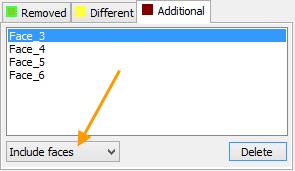
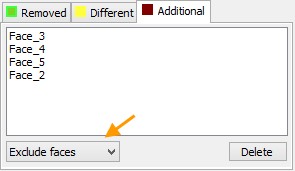
The Additional tab was added to the parameters window of the command. The following options are available on the tab:
●Include faces;
●Exclude faces.
Include faces. The option allows to specify faces that will be included in the shell creation operation.
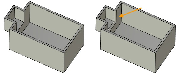
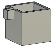
For the protruding part of the body in the figure below, you need to create a shell.
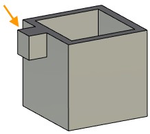
The system cannot determine the geometry independently, so you need to manually include the faces in the operation.
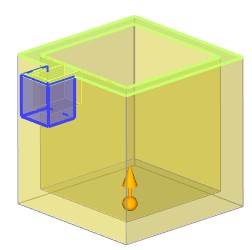
Result:
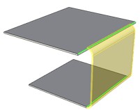
Exclude faces. The option allows to specify faces, for which the shell will not be created.
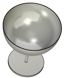
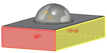
Operation Shell is sometimes applied not to all faces of the body, but only to their parts. In the example below, we need to build a shell only for the spherical part of the body.
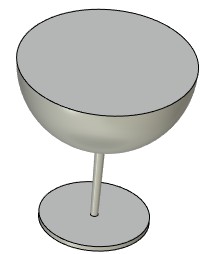
After selecting the removed face, the shell will be built for the entire body, and not just for its spherical part.
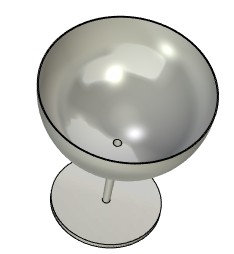
To get the desired result, you need to exclude faces from the operation.
To do this, you should specify four faces that will be excluded from the operation on the Additional tab.
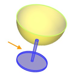
The required model will be obtained.
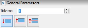
Other Changes in Operation
Buttons that allow to specify direction of faces offset upon operation creation appeared in the parameters window.
Dynamic preview and Use draggers options were added to the Shell command.
If the Use draggers option is active, a single dragger appears, which specifies the wall thickness and the direction of a face offset.
A dragger also appears for each face that was added to the Additional tab. It allows you to specify the direction of offset and the wall thickness for this face.
The user interface and the functionality of Edge Blend operation have been refined. The stability of operation algorithms in complex cases increased. Obvious buttons for switching of command operating modes have been added to its interface. The lists of elements are made resizable. In Variable (Circular) and Variable (Ellipse) modes information about operation parameters at specific points is displayed directly in the lists of positions.
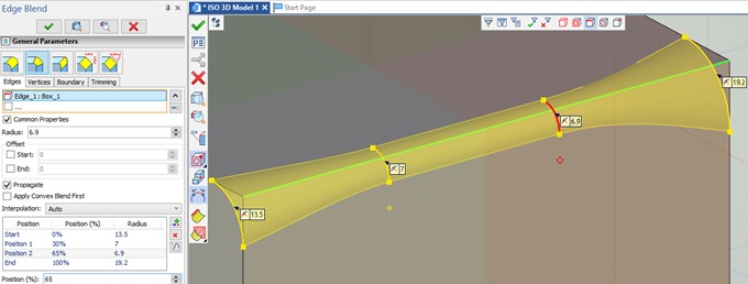
A new type of blending was added - spherical. Special icons are used to select the type of blending.

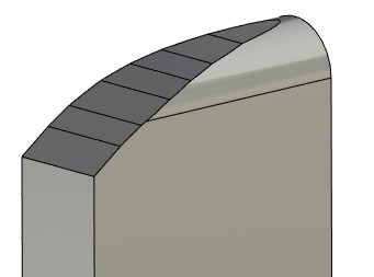
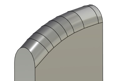
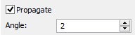
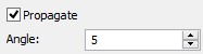
The Angle allows to set angle at which the conjugate faces of the center wall participate in blending. The parameter is available only when the option Propagate is active.
|
|
|
|
A new section was added to the parameters of the operation - Result.
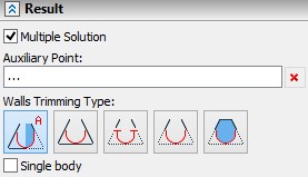
The Multiple solution option allows to specify exactly, which surface should be blended when performing operation. To define this surface, you need to specify a point in the scene using the Auxiliary point option.
For example, we need to blend the model shown in the figure below.
With normal blending, both halves of the detail will be blended.
To blend only one part of the model, you need to select an auxiliary point. Only the closest to the given point faces will be blended.
When using the option the parameter Trimming by walls should be in the By both walls mode.
Automenu option Smooth face chain selection mode ![]() allows you to simplify the selection of faces to create an operation.
allows you to simplify the selection of faces to create an operation.
If the option is active, then after selecting a face, the system checks for the presence of smoothly conjugate faces next to it. If such faces exist, they are also added to the operation.
Options for defining type of walls trimming were added to the command.
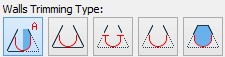
![]() No Trim - blending face is created separately. Result is a separate surface.
No Trim - blending face is created separately. Result is a separate surface.
![]() Trim Both - Result is a separate surface.
Trim Both - Result is a separate surface.
![]() Trim and Sew - If the blended surface lies between two different bodies, then they are united into one body.
Trim and Sew - If the blended surface lies between two different bodies, then they are united into one body.
![]() Create Solid - if the result of blending forms a closed space, a solid body is created.
Create Solid - if the result of blending forms a closed space, a solid body is created.
Now you can create blend as a separate body. To do this, you should enable the Single body option.
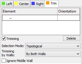
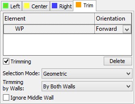
The Trim tabs was added to the command. It allows you to select elements in the scene to create a trimming operation, and allows you to build blending of the desired shape for bodies with different length.
The Trimming by walls mode is enabled by default. In this mode, you can select the mode for Trimming by walls parameter. The option Trimming by walls allows you to process bodies with different lengths.
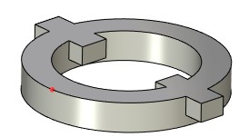
For example, the blending of three separate sheet bodies was created.
No Trim. Blending surface is not limited.
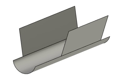
By Both Walls. Blending surface is limited by length of the both walls.
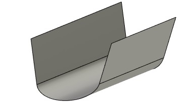
By Short. The blending will be created according to the length of the short wall.
By Long. The blending will be created according to the length of the long wall.
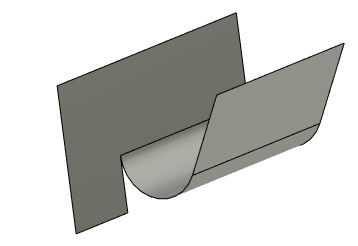
The Ignore Center Wall option allows to ignore the center wall when creating a blending surface. For example, the option may be useful when you create a body with a trim in the By Long mode.
|
|
The option is enabled |
The option is disabled |
User can set element in the scene according to which the geometry will be trimmed.
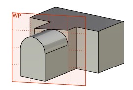
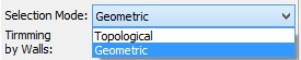
You can choose topological (face, edge, etc.) or geometric (plane, surface) elements to create a crop.
You can also specify direction of trimming according to the selected element.
The Trim flag allows to specify type of the body trimming. If the flag Trim is enabled, the boundaries of the blending are defined by the position of selected element.
Otherwise, the system creates trimming perpendicular to the point that is formed by one of the following methods:
- for the spherical blending it is the intersection of the selected element and the blending vertex.
- for disk-type blending, this is the intersection of the selected element and the specified guide.
A set of options for the Spring command is expended to increase the convenience of the command.
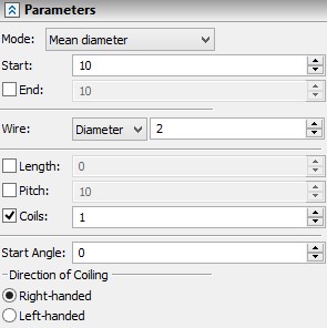
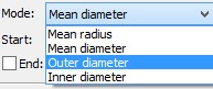
The Mode option allows you to specify whether the radius or diameter will be used to specify beginning and end of the spring. Diameter can be specified as inner or outer.
Now it is possible to specify the radius/diameter of the wire of the spring using the Wire option.
The spring can be created using any combination of input data: Length, Pitch and Coils. The system keeps track of the minimum number of parameters required to create a spring.
The Start Angle option was added. The option allows you to set the start angle of the spring.
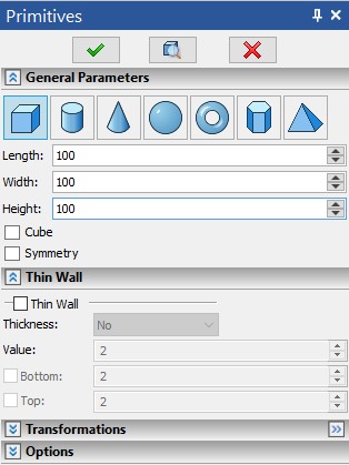
“Primitives” Operation Group
To increase the usability of the Primitives command group, a new toolbar has been added to the options dialog of all primitives. It allows you to switch between the primitive types in the mode of command running:
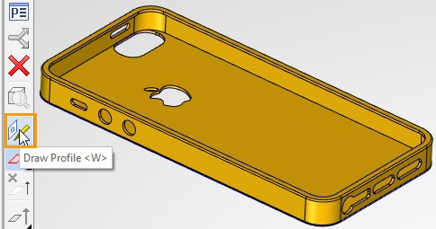
Creation of Profiles in Commands of 3D Operations
Now you can create a profile in a transparent mode from the commands Extrusion, Rotation, Sheet Metal Part, etc. Activate option Draw profile to do this.
After the option activation, the system prompts you to select the face or plane on which to draw.
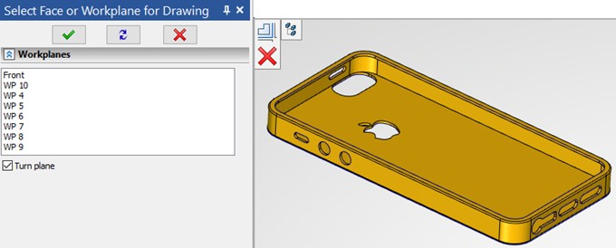
After plane selection the system starts drawing on a workplane or face. When the drawing is complete, the system returns to the 3D modeling command and uses the profile to create the model.
If you do not have any profiles when you call the 3D modeling command, the system automatically prompts you to select a face or plane to create a profile.
Due to this mechanism, some 2D drawing commands are now available in the 3D scene. After they are called, you are prompted to select a face or plane to create a drawing.
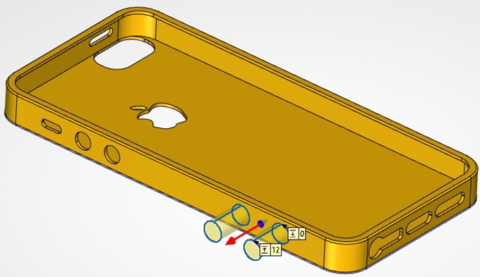
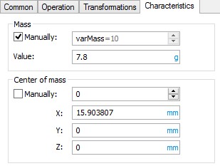
Manual Mass-Inertia Characteristics Control
Now it is possible to manually control the mass-inertial characteristics of bodies, 3D fragments and surfaces in the system. To do this, the "Characteristics" tab has been added to the parameters of the elements. In order for the system to take into account the specified parameter, you need to activate the corresponding flag. To specify a value, you can use either constant values, variables or expressions.
Manually entered values are used:
●when calculating the total mass and the coordinates of the product center of mass;
●in the Measure command, when receiving the mass using the appropriate functions in the variable editor;
●when forming BOM and other reporting documents.
This mechanism can be used when working with large-scale models of products, as well as purchased products, when there is no accurate model of the product, and its mass-dimensional parameters are specified in the form of requirements/data in the technical passport.
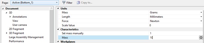
Besides specifying mass of separate bodies, it is available to specify characteristics of the whole document manually. In this case, the value is set in the Document parameters command. It will be useful when you create element libraries, and the fragment mass is not calculated automatically but is manually specified regardless of the number of bodies in the subassembly.
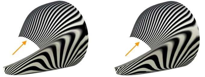
A possibility of simplifying a spline surface was added to the command. If faces simplification cannot be done by reducing it to the standard face type, i.e. plane, cylinder, etc., then faces are replaced by one face with a smooth spline surface. This simplification improves the quality of the surface. The resulting surface is less demanding on computer resources.
The basic algorithms for operating with faces have been updated. In particular, in the operations "Transform faces", "Replace faces", "Change faces" processing of the faces that are changed to other faces of the model with the correct processing of intersections was added. As a result of such processing, the composition of body elements can change (edges and faces appear or disappear). Example of the «Transform Faces» operation: