3D Geometry


3D Geometry |
|
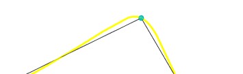
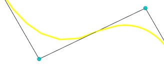
The ability to build a curve that does not require an accurate passage through all specified points is added. The new mechanism allows smoothing a large number of points of a smooth curve with a given accuracy.
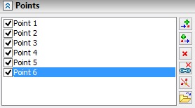
The construction of such a curve occurs in the Spline through points mode. An Interpolation point flag is available next to each of the points. All the default points are interpolation points. If you remove a flag from a point, then the deviation will be taken into account for the point.
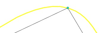
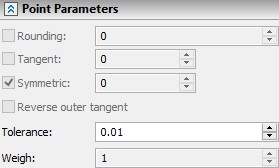
The value of the curve tolerance from the points is given immediately for the entire spline in the parameters dialog.
The list of points can be downloaded from a TXT or CSV file using the Load from file. To specify each point you need three coordinates, which you can enter from a new line.
In the Spline through points mode, the Straighten by chord option was added.
|
|
|
|
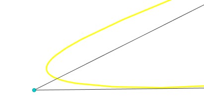
For the Spline by polygon the Weight parameter is added. The greater the weight of the point, the closer the curve passes to it.
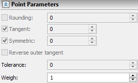
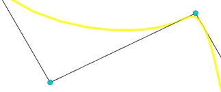
For Spline through Points, the option Symmetric is added. The option allows you to separately control the tangency at a point.
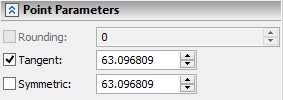
Now when you connect two routes, it is possible to specify a touch at the end to control the boundary conditions.
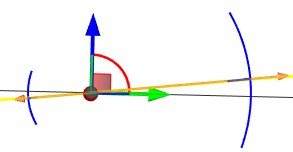
The command 3PB: Helix 3D Path was added. The operation creates a helix path that you can use to translate a profile of any shape.
You can specify a graph for a helix path that will control its parameters.
You can specify the length and pitch, as well as other options in the operation parameters.
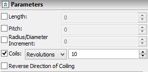
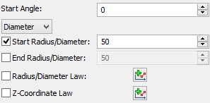
It is possible to build cylindrical, flat and conical spirals.
In addition, you can use graphs of side generating line and pitch changes to create helixes.
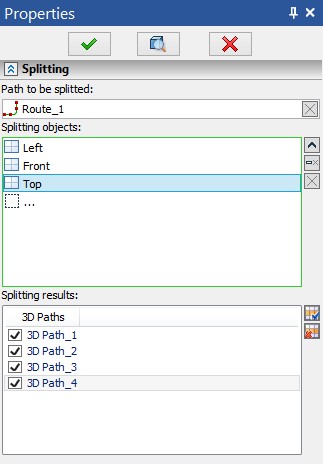
The option for creation of 3D paths by splitting of the existing 3D path using other model elements was added. As the result of operation, copies of the selected path are created. The copies corresponds to the sections between the elements used for separation.
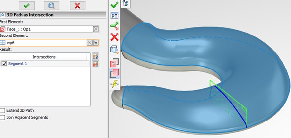
3D-path as Intersection of Elements
The 3D-path as Intersection function has been updated. The operation allows to select any types of elements (all body types, profiles, separate faces) to construct wire geometry at their intersection. The user can choose one element pointed as First and arbitrary number of Second elements. At the same time in case of multiple intersections, the user can choose required intersection piece both in the list and by click in 3D-scene.
We have revised the options for creating of 3D-path based on 2D elements lying on the workplane. The options for creating of 3D-paths based on hatches and construction lines are united in one command. In addition to existing opportunities, the ability to select graphic lines as source elements is added.

The Additional Snap option allows to set additional snaps for created 3D-element that are supported by previous releases of T-FLEX CAD.
A possibility to create 3D axis was added to solve the following tasks:
●Possibility to use the axis for specifying an axis of rotation or a direction upon operations creation;
●Possibility to preliminary create all axes of the model for the following projection creation;
●Possibility to create 3D dimensions: between axes, from axis to the workplane, etc.
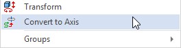
You should select the Convert to axis command in the context menu of the selected geometry to create an axis.
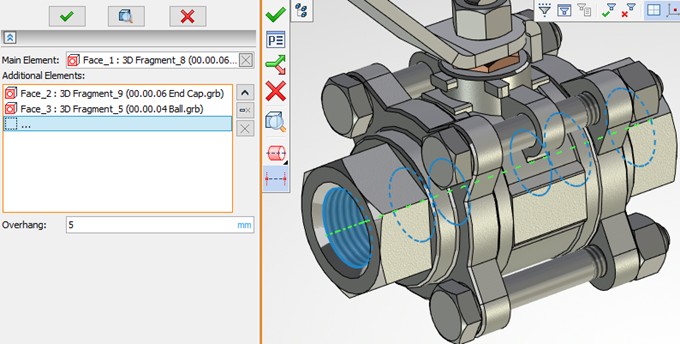
A new command 3D Axis was added for simple creation of 3D axes on the basis of surfaces of rotation and edges. The command allows to create rectilinear axes based on the elements of rotation - cylindrical, conical, toroidal, as well as circular edges. As additional elements for specifying the dimensions of the created axis, you can select any other elements of the model.
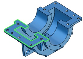
A possibility to create a profile using wire geometry was added. The Construct 3D profile by wire geometry ![]() automenu option is used for it.
automenu option is used for it.
You can also select edges of the already existing models for quick profile construction using the option.
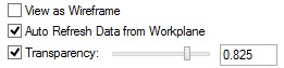
Now it is possible to change the transparency of 3D profiles when drawing in 3D window. To do this, the "View as Wireframe" flag and transparency controls were added to the profile parameters.
Building 3D Profiles by Unfolding
Essential improvements were made in functionality of creating 3D profiles by unfolding. Instead of several ways to unfold faces, one mode was added, "Unfold Surface", which unifies all the methods of unfolding faces. When several adjacent faces are selected, the "Delete redundant edges" flag appears which simplifies the topology of the resulting profile.
When unfolding surfaces, it is now possible to select non-rotating surfaces. To solve the problem of development of such a surface or set of surfaces, an iterative algorithm is implemented.
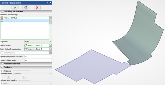
For this algorithm, the accuracy parameters of the intermediate computational grid used for iterative calculations can be specified.