Example of Working with Auxiliary Lines of 2D Projection |
  
|
Let's say, we have a 3D model of a workshop with machinery and other equipment. However, in the workshop layout drawing we just need a simple scheme, instead of the precise detailed image.
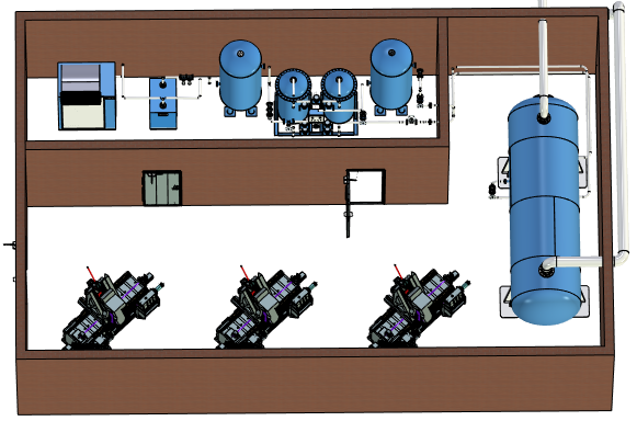
First we create a top view 2D projection of the workshop and enable the Create Auxiliary Lines checkbox in the Lines tab of the projection parameters.
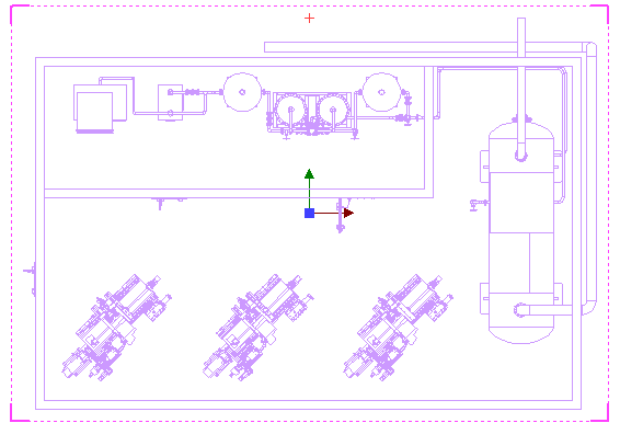
Then we select the wall lines, which need to be included into the scheme, and disable the Auxiliary checkbox in their contextual menu.
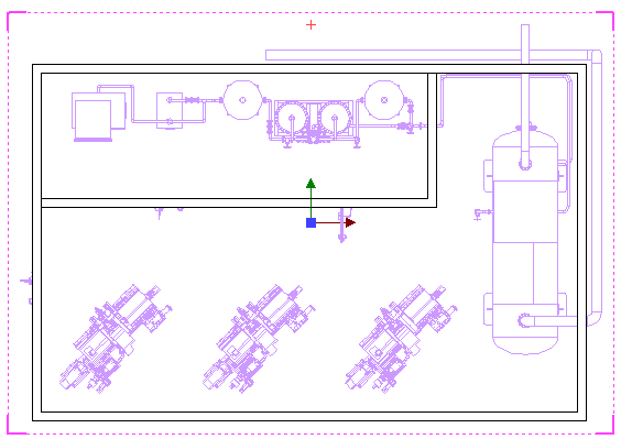
For the rest of the elements we draw the simple contours and axes manually, using the automatic constraints creation and snapping the created lines to the auxiliary lines projected from the 3D model.
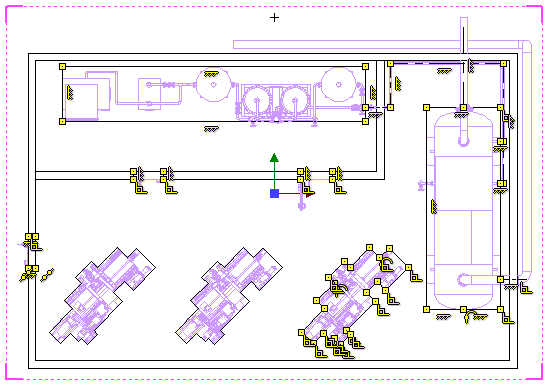
In the end we add the calouts also snapping them to the auxiliary lines of the 2D projection. Now, let's hide constructions, in order to see the final appearance of the layout drawing.
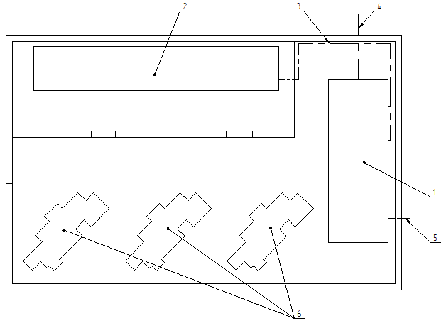
Regardless of the fact, that most of the lines in the layout drawing are created manually, they are indirectly linked to the 3D model via constraining them in relation to the lines of the 2D projection. But the projection lines themselves are not displayed (except the walls). Upon changes in the layout of the 3D model, the layout drawing will be regenerated accordingly.
In order to increase the performance of the layout drawing recalculation, you may additionally delete the 2D projection lines not related to the layout lines.