Snapping Construction Circle's Tangency Configuration to Node |
  
|
When creating construction circles, the following option becomes available in the automenu, upon selecting two circles or straight lines as tangents::
|
<G> |
Set Relation with Node |
Upon activating the option, select the desired 2D node by clicking it with ![]() . In result, upon further changes in geometry of parent elements, the circle will be regenerated in such a way that it passes is as close as possible to the node.
. In result, upon further changes in geometry of parent elements, the circle will be regenerated in such a way that it passes is as close as possible to the node.
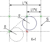
Example given below shows us how this capability can be used. Location of straight lines on the drawing with respect to the axis of symmetry S is controlled by the value of the variable K. Two circles are constructed as tangent to two lines. In addition, the tangency configuration of the circle shown in continuous line is snapped to the node highlighted in red. The tangency configuration snapping is not specified for the second circle.
The left figure shows the initial location of the drawing’s elements, when K=1.
The right figure shows, how the drawing will be changed when the variable’s value is К=-1. The circle, whose tangency configuration was snapped to the node, was reconstructed symmetrically. The second circle, that is constructed without spanning tangency configuration to a node, changed its location in relation to the tangent lines.


In order to cancel snapping of tangency configuration to a node, use the following option
|
<B> |
Break Link with 2D Node |
See Also:
•Construction Circle with Two Tangents, through Node