Contour Check |
  
|
The command can be called in one of the following ways:
Icon |
Ribbon |
|---|---|
|
Measure > Contour Check > Contour Check Workplane > Analysis > Contour Check |
Keyboard |
Textual Menu |
<QP> |
Tools > Geometry Analysis > Contour Check |

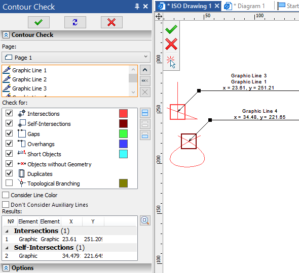
The command checks contours formed by graphic lines for errors on an active workplane, on a drawing page or within active drawing view. It is useful on active WP, when checking contours, that will be used for creating 3D profiles. When working with a drawing, you can select a Page to be checked using the drop-down list in the top of the command's parameters window. If there are no active drawing views on the selected page, then the command checks elements not belonging to views. If there are is an active drawing view, then the command checks content of such view. When working with a 3D scene with no active workplanes, the Page drop-down list contains all existing workplanes. Selecting a workplane in the list activates it. When working on an active workplane, the current workplane is selected automatically and there are no other options in the drop-down list.
Below the Page drop-down list there is the list of lines to be checked. Upon calling the command, lines can be added to the list using ![]() . Calling the command with pre-selected lines automatically adds such lines into the list. Launching the check with empty list leads to checking all available graphic lines. The list of lines to be checked can be managed using the Expand
. Calling the command with pre-selected lines automatically adds such lines into the list. Launching the check with empty list leads to checking all available graphic lines. The list of lines to be checked can be managed using the Expand ![]() , Collapse
, Collapse ![]() , Delete element from the List
, Delete element from the List ![]() and Clear
and Clear ![]() buttons.
buttons.
In the panel below you can select categories to Check for:
![]() Intersections
Intersections
Intersections of two or more lines.
![]() Self-Intersections
Self-Intersections
Lines intersecting themselves.
![]() Gaps
Gaps
Distance between lines within the specified range.
![]() Overhangs
Overhangs
Partially coinciding lines.
![]() Short Objects
Short Objects
Lines, whose lengths fall into the specified range.
![]() Objects without Geometry
Objects without Geometry
Objects, whose geometry cannot be constructed. For instance, if you construct an arc by three nodes first, and later make such nodes lay on the same straight line, then the arc will become the object without geometry.
![]() Duplicates
Duplicates
Fully coinciding lines.
![]() Topological Branching
Topological Branching
Starting/ending points of more than two lines.
There are color samples near some of the categories in the Check for panel. The results of the corresponding type get outlined in the drawing or WP using such colors, upon performing the check. Colors can be customized using the system options dialog (Options > Colors > Contour Check). The system checks for categories, whose checkboxes are enabled. Checkboxes could be enabled or disabled by clicking ![]() them directly or using buttons in the right side of the panel (
them directly or using buttons in the right side of the panel (![]() Select All,
Select All, ![]() Unselect All,
Unselect All, ![]() Invert Selection).
Invert Selection).
Following checkboxes are available below the Check for panel:
•Consider Line Color
The checkbox is disabled by default. Enabling it excludes from the results ![]() Intersections,
Intersections, ![]() Gaps,
Gaps, ![]() Overhangs and
Overhangs and ![]() Topological Branching between lines of different colors.
Topological Branching between lines of different colors.
•Don't Consider Auxiliary Lines
This checkbox is enabled by default, so auxiliary lines are ignored by check. If you disable this checkbox, all selected lines will be checked.
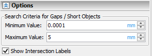
Following Options are available in the eponymous tab of the command's parameters window:

•Search Criteria for Gaps / Short Objects
![]() Gaps and
Gaps and ![]() Short Objects are detected if gap value or object length fall within range between Minimum and Maximum Value. The range includes the minimum value, but doesn't include the maximum.
Short Objects are detected if gap value or object length fall within range between Minimum and Maximum Value. The range includes the minimum value, but doesn't include the maximum.
•Show Intersection Labels
If this checkbox is enabled, then labels will appear on a drawing or WP upon performing the check. Each label marks an intersection point and contain its coordinates as well as names of intersecting lines. Precision of coordinates is defined by document parameters (Document Parameters > Page > View > Linear > Precision).
Set the desired check parameters and press ![]() , <Ctrl>+<Enter> or <Enter>. The list of results will appear in the Results panel. Results in the list are grouped by categories. You can fold a group by clicking the
, <Ctrl>+<Enter> or <Enter>. The list of results will appear in the Results panel. Results in the list are grouped by categories. You can fold a group by clicking the ![]() button, which is located to the left side of a body name. When folded, the button changes to
button, which is located to the left side of a body name. When folded, the button changes to ![]() . Click it again to unfold a group. The number of results in a group is shown in brackets to the right side of a group's name. Index number (№), names of affected lines (Element 1, Element 2), as well as X and Y coordinates (if applicable), are shown for each result in the list. Endpoint's coordinates of one of the affected lines are shown for gaps, coordinates of intersection point are shown for intersections and self-intersections, coordinates of branching point are shown for topological branchings. Results can be selected in the list using
. Click it again to unfold a group. The number of results in a group is shown in brackets to the right side of a group's name. Index number (№), names of affected lines (Element 1, Element 2), as well as X and Y coordinates (if applicable), are shown for each result in the list. Endpoint's coordinates of one of the affected lines are shown for gaps, coordinates of intersection point are shown for intersections and self-intersections, coordinates of branching point are shown for topological branchings. Results can be selected in the list using ![]() . As you select a result in the list, affected lines get selected in the drawing/WP and an outline (if applicable) changes color to light magenta. You can
. As you select a result in the list, affected lines get selected in the drawing/WP and an outline (if applicable) changes color to light magenta. You can ![]() Zoom In camera to the selected result using button located at right side of the results list.
Zoom In camera to the selected result using button located at right side of the results list.
Upon receiving check results you may change command's parameters and launch check again (![]() , <Ctrl>+<Enter> or <Enter>), or exit the command (
, <Ctrl>+<Enter> or <Enter>), or exit the command (![]() ,
, ![]() , <Esc>, <Shift>+<Esc>, <X>).
, <Esc>, <Shift>+<Esc>, <X>).