Position of Dimension Line and Value |
  
|
Upon selecting source objects, a preview of dimension appears. Position of witness lines is defined by the source of objects. dimension line follows the cursor along the witness lines and dimension value follows the cursor along the dimension line. Next, if you click ![]() at an empty space in drawing, then the positions of dimension line and value get fixated and the dimension creation ends. Alternatively, instead of clicking an empty space, you can select
at an empty space in drawing, then the positions of dimension line and value get fixated and the dimension creation ends. Alternatively, instead of clicking an empty space, you can select ![]() one of the existing points of the drawing image (a characteristic point of a graphic line, a 2D node, an intersection of construction lines) using object snappings. In such case, the dimension line gets snapped to the selected point, but the dimension value continues following the cursor along the dimension line. Then, you should specify the position of the value by pressing
one of the existing points of the drawing image (a characteristic point of a graphic line, a 2D node, an intersection of construction lines) using object snappings. In such case, the dimension line gets snapped to the selected point, but the dimension value continues following the cursor along the dimension line. Then, you should specify the position of the value by pressing ![]() again, which ends the dimension creation. A dimension value may also be snapped to an existing point using object snappings. Snapping a dimension line or a dimension value to an existing point creates an associative link, i.e., if the position of the selected point changes, as a result of further editing, then the linked dimension line or value with follow the point.
again, which ends the dimension creation. A dimension value may also be snapped to an existing point using object snappings. Snapping a dimension line or a dimension value to an existing point creates an associative link, i.e., if the position of the selected point changes, as a result of further editing, then the linked dimension line or value with follow the point.
Dimension components may also be positioned using the following automenu option:
|
<Space> |
Place dimension in absolute coordinates |
It sequentially switches dimension value positioning modes.
The option is not available for radial and leader dimensions. When creating dimensions from one baseline, or a dimension chain, the option is also not available, however it can be used later, when editing individual resulting dimensions. For level markers, the option just fixates the value and switches shoulder direction. For dimensions of other categories, the option works as described below.
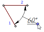
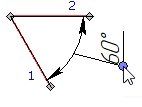
As was said before, upon selecting source objects, dimension line follows the cursor along the witness lines and dimension value follows the cursor along the dimension line.
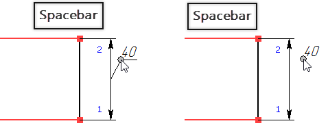
If you activate the ![]() option for the first time, the position of the dimension line gets fixated, so only the value still follows the cursor along the dimension line. Then, you can either specify the position of the value by pressing
option for the first time, the position of the dimension line gets fixated, so only the value still follows the cursor along the dimension line. Then, you can either specify the position of the value by pressing ![]() again, which ends the dimension creation, or activate the
again, which ends the dimension creation, or activate the ![]() option again.
option again.
If you activate the ![]() option for the second time, the horizontal shoulder will be added directly connected to the dimension line itself (if the value is inside witness lines) or to its continuation (if the value is outside witness lines). The position of the shoulder is defined by the position of the value at the moment of activating the
option for the second time, the horizontal shoulder will be added directly connected to the dimension line itself (if the value is inside witness lines) or to its continuation (if the value is outside witness lines). The position of the shoulder is defined by the position of the value at the moment of activating the ![]() option. The orientation of such shoulder cannot be changed. Upon adding the shoulder, the value follows the cursor horizontally along the shoulder. Then, you can either specify the position of the value by pressing
option. The orientation of such shoulder cannot be changed. Upon adding the shoulder, the value follows the cursor horizontally along the shoulder. Then, you can either specify the position of the value by pressing ![]() again, which ends the dimension creation, or activate the
again, which ends the dimension creation, or activate the ![]() option again.
option again.
The second positioning mode is not available for horizontal dimension, so activating the ![]() option for the second time for such dimensions is similar to activating it for the third time for other dimensions and so on.
option for the second time for such dimensions is similar to activating it for the third time for other dimensions and so on.

If you activate the ![]() option for the third time, the leader line with shoulder will be added connected to the midpoint of the dimension line, and then the shoulder and value follow the cursor in all directions. The orientation of such shoulder can be changed using the separate automenu option described below. Then, you can either specify the position of the shoulder by pressing
option for the third time, the leader line with shoulder will be added connected to the midpoint of the dimension line, and then the shoulder and value follow the cursor in all directions. The orientation of such shoulder can be changed using the separate automenu option described below. Then, you can either specify the position of the shoulder by pressing ![]() again, which ends the dimension creation, or activate the
again, which ends the dimension creation, or activate the ![]() option again.
option again.
If you activate the ![]() option for the fourth time, the leader line with shoulder will disappear, so only the value will follow the cursor in all directions being visually disconnected from the dimension line. Then, you can either specify the position of the value by pressing
option for the fourth time, the leader line with shoulder will disappear, so only the value will follow the cursor in all directions being visually disconnected from the dimension line. Then, you can either specify the position of the value by pressing ![]() again, which ends the dimension creation, or activate the
again, which ends the dimension creation, or activate the ![]() option again.
option again.
Activating the ![]() option for the fifth time restores the default positioning mode, where dimension line and dimension value follow the cursor simultaneously.
option for the fifth time restores the default positioning mode, where dimension line and dimension value follow the cursor simultaneously.
Even if the cursor is pointed at some existing point at the moment of activating the ![]() option, it doesn't create associative links.
option, it doesn't create associative links.

Upon creating a dimension, position of its components may be edited via manipulators. When doing so, you can also snap them to existing point via object snappings, which results in creating an associative link between the selected point and the corresponding component of the dimension.

In order to cancel snapping to a point for a particular component of dimension, activate the manipulator, which controls the position of such component, and then specify the new position without snapping it to a point.
in order to cancel snappings to points for all components of the current dimension, activate the following automenu option:
|
<K> |
Break relations |
Upon activating this option, you have to re-define positions of the dimension line and value.
If a dimension doesn't have a shoulder, then the following automenu option is available during its creation and editing:
|
<J> |
Center dimension text |
By default, the centering is disabled, so the dimension value follows the cursor along the dimension line. If you enable the centering, then the value will remain in the middle between witness lines, regardless of the cursor position and distance between witness lines.
if a dimension has a leader line with shoulder, then the following automenu option is available during its creation and editing:
The option sequentially switches between the following shoulder orientation options: horizontal right, horizontal left, vertical up, vertical down. If dimension has no shoulders, the option has no effect. Leader dimensions and level markers may only have horizontal shoulders.


