Manual Insertion of 3D Fragment by 2D Fragment without Using Layout |
  
|
Upon calling the ![]() 3D fragment insertion command you can select a 2D fragment already inserted into the current document by clicking it with
3D fragment insertion command you can select a 2D fragment already inserted into the current document by clicking it with ![]() in 3D scene, in drawing, in the 3D model tree or in the
in 3D scene, in drawing, in the 3D model tree or in the ![]() Assembly Structure window. It allows you to insert a 3D fragment based on a 3D model stored in the document of the selected 2D fragment.
Assembly Structure window. It allows you to insert a 3D fragment based on a 3D model stored in the document of the selected 2D fragment.
If the selected 2D fragment is inserted into a ![]() normal drawing page, then its selection will result in usual insertion of a 3D fragment. This doesn't create any associativity between 2D and 3D fragments. Such method of insertion just simplifies the selection of 3D fragment, allowing you click its image in drawing instead of specifying a file path. By default, the 3D fragment is placed at the global LCS origin, regardless of the 2D fragment's position in drawing. You may also apply additional transformations and customize other parameters of the 3D fragment, if necessary, in the same way, as it is usually done in the 3D fragment insertion command.
normal drawing page, then its selection will result in usual insertion of a 3D fragment. This doesn't create any associativity between 2D and 3D fragments. Such method of insertion just simplifies the selection of 3D fragment, allowing you click its image in drawing instead of specifying a file path. By default, the 3D fragment is placed at the global LCS origin, regardless of the 2D fragment's position in drawing. You may also apply additional transformations and customize other parameters of the 3D fragment, if necessary, in the same way, as it is usually done in the 3D fragment insertion command.
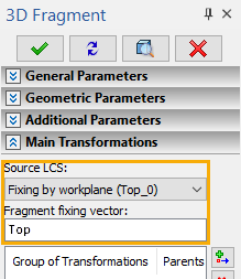
If the selected 2D fragment is inserted into a ![]() workplane page, then, upon its selection, the 3D fragment will be automatically positioned in 3D scene in relation to such workplane in accordance with the position of the 2D fragment on the workplane page. Manipulators of 3D fragment's transformations are not displayed in such case. The Fixing by workplane option gets automatically selected in the Source LCS drop-down list of 3D fragment's parameters; the name of the corresponding 2D fragment's fixing vector is indicated below (if such vector was used for inserting the 2D fragment).
workplane page, then, upon its selection, the 3D fragment will be automatically positioned in 3D scene in relation to such workplane in accordance with the position of the 2D fragment on the workplane page. Manipulators of 3D fragment's transformations are not displayed in such case. The Fixing by workplane option gets automatically selected in the Source LCS drop-down list of 3D fragment's parameters; the name of the corresponding 2D fragment's fixing vector is indicated below (if such vector was used for inserting the 2D fragment).

Upon confirming the insertion of the 3D fragment (![]() or <Ctrl>+<Enter>). , the associative link between positions of the 2D and 3D fragments is kept. I.e., if you manually move or rotate the 2D fragment on its page, then the 3D fragment will be automatically moved or rotated in 3D scene in the same way, upon updating the model. However, the affect imposed on 2D fragment by manual repositioning and rotation of the 3D fragment depends on the status of the following option, which is available in the automenu of the 3D fragment's editing command:
or <Ctrl>+<Enter>). , the associative link between positions of the 2D and 3D fragments is kept. I.e., if you manually move or rotate the 2D fragment on its page, then the 3D fragment will be automatically moved or rotated in 3D scene in the same way, upon updating the model. However, the affect imposed on 2D fragment by manual repositioning and rotation of the 3D fragment depends on the status of the following option, which is available in the automenu of the 3D fragment's editing command:
|
<L> |
Layout mode |
This option is active by default for 3D fragments with fixing by workplane. When it's active, 3D fragment transformations manipulators, which would allow to detach the fragment from its fixing workplane, are hidden, so the fragment can be moved and rotated only within such workplane. Transformations applied to 3D fragment, while the option is active, are also automatically applied to corresponding 2D fragment. Transformations applied to 3D fragment, while the option is not active, do not affect corresponding 2D fragment.


Instead of this option, you may also insert 3D fragments using the special ![]() Layout command, which additionally allows linking 3D fragment's position to 2D fragment's position on a normal drawing page, inserting multiple 3D fragments at once and selecting a different WP for positioning the 3D fragment. The detailed information on this command is available in the Manual Insertion of 3D Fragments by 2D Fragments Using Layout section.
Layout command, which additionally allows linking 3D fragment's position to 2D fragment's position on a normal drawing page, inserting multiple 3D fragments at once and selecting a different WP for positioning the 3D fragment. The detailed information on this command is available in the Manual Insertion of 3D Fragments by 2D Fragments Using Layout section.